Automatic stent inspection system

a stent and automatic technology, applied in the field of stent inspection, can solve the problems of inability to perform all the inspection tasks mentioned above in an automatic manner, laborious and time-consuming manual stent inspection process, and patient death or serious injuries

Inactive Publication Date: 2010-12-09
JIN JU
View PDF4 Cites 28 Cited by
  • Summary
  • Abstract
  • Description
  • Claims
  • Application Information

AI Technical Summary

Benefits of technology

[0017]The object of the present invention is to provide a fully automated stent inspection system. It comprises three illuminators: an external illuminator, a co-axial illuminator and a telecentric illuminator. The external and co-axial illuminators provide uniformly diffused illumination across both the interior and exterior surfaces of a stent, while the telecentric illuminator provides telecentric backlight. The fully automated stent inspection system also comprises an optical imaging subsystem to image a portion of stent, a surface-scanning profiling subsystem to characterize the surface condition and measure the 3D profile of a stent wire

Problems solved by technology

Since stents are implanted into coronary arteries and other flood flow paths, a failure in function of a stent could lead to death or serious injuries of patients.
Unfortunately, at present time, existing automatic or semi-automatic stent inspection tools can measure some of the dimensional features and perform some limited visua

Method used


Image

  • Automatic stent inspection system
  • Automatic stent inspection system
  • Automatic stent inspection system

Examples


second embodiment

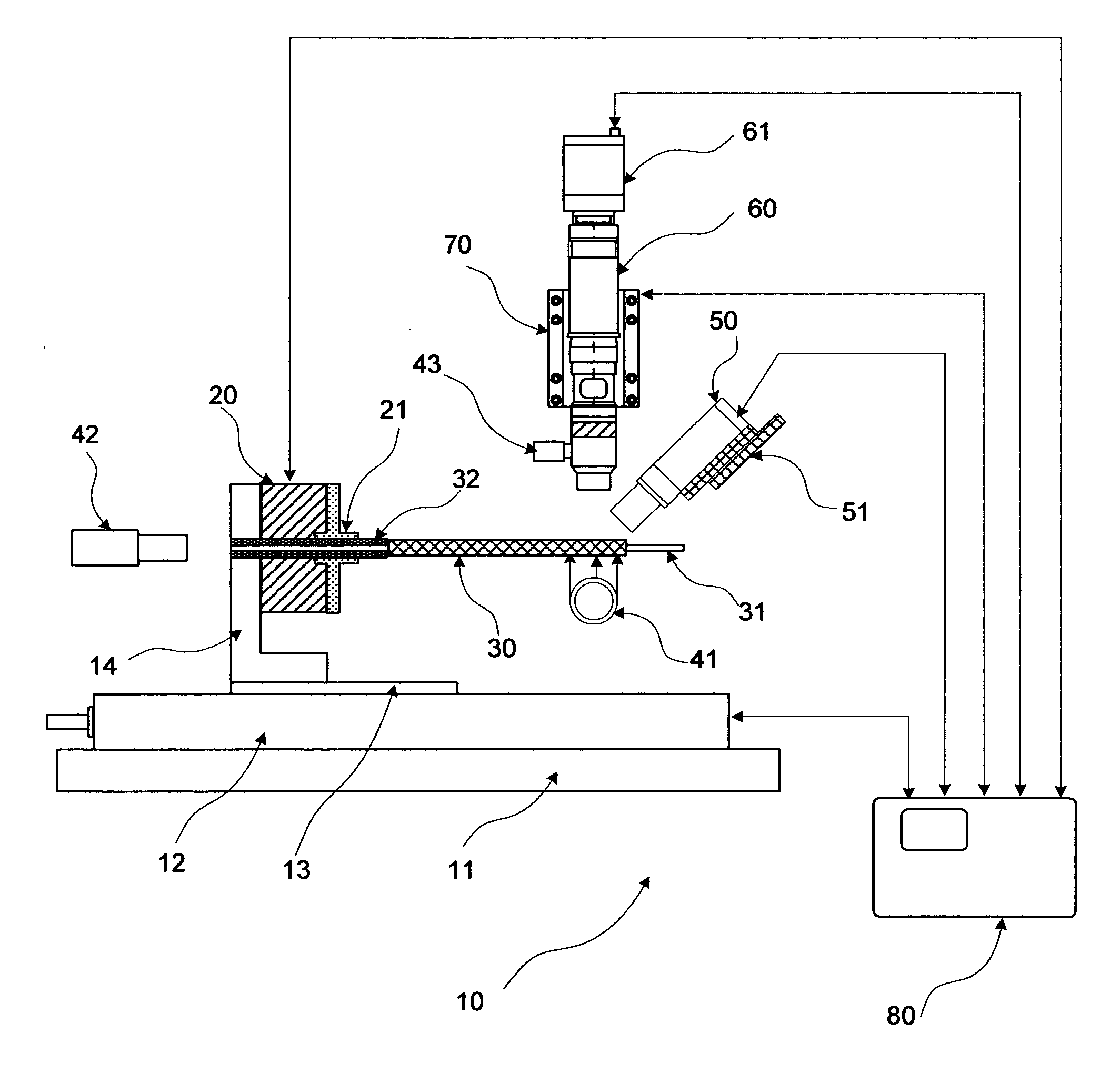
[0064]Now referring to FIGS. 5 and 13, in the present disclosure, the system 10 is used to inspect a stent with relatively large geometric dimensions. In this case, the magnification of the zoom lens 63 can be set to the lower end, increasing both the field of view and the depth of the field of the of optical imaging subsystem 60. As a result, the depth of field becomes large enough to compensate variations of the vertical position of the stent 30 due to stage motion and dimensional derivations. It becomes unnecessary to actively control the movement of the vertical stage 70 to keep the working distance of the optical imaging subsystem 60 constant, as described in the above embodiment. In other words, the auto-focusing function performed by the vertical stage 70 can be turned off. Instead, the vertical stage 70 can be set to the pre-determined position and keep unchanged during the inspection cycle: Steps 1 through 4 described above. By doing so, the time spent on auto-focus adjustm...

third embodiment

[0066]Now referring to FIG. 1 and FIGS. 14A-D, in the present disclosure, the system 10 is used to inspect a drug eluting stent, or DES. A drug eluting stent consists of a metallic stent covered with drug-containing film to prolong drug release. In this case, the defects to be detected are film related, such as voids, flakes, and bridges across struts shown in FIGS. 14A-C. To achieve best detection performance, referring to FIG. 5, a proper type of filter 67 of the optical imaging subsystem 60 is utilized for each specific drug films. The types of the filter 67 include, but not limited to, red, green, blue, bandpass, short-pass, long-pass, UV and IR filters, as well as polarizers. Also the defect detection and classification software installed in the control console 80 uses image processing algorithms different from those used in a bare metal stent inspection.

[0067]Furthermore, the surface-scan profiling subsystem 50 is used to measure surface roughness, thickness and coating unifor...


PUM


Abstract

A fully automated inspection system provides for inspection, measurement and characterization of a wire mesh tube, particularly a stent. The system uses an optical imaging subsystem to capture high resolution color images of both exterior and interior surfaces of a stent. Defects are defected by processing the captured images using proprietary algorithms. Geometric dimensional features of a stent are measured by processing the stitched 2-D map of the stent. In addition, a surface-scanning profiling subsystem is used to measure the surface roughness of drug films or metallic surfaces. It also measures the 3-D profile of a stent strut.

Description

CROSS-REFERENCE TO RELATED APPLICATIONS[0001]Not Applicable.STATEMENT REGARDING FEDERALLY SPONSORED RESEARCH OR DEVELOPMENT[0002]Not Applicable.REFERENCE TO SEQUENCE LISTING, A TABLE, OR A COMPUTER PROGRAM LISTING COMPACT DISC APPENDIX[0003]Not Applicable.FIELD OF THE INVENTION[0004]The present disclosure relates to inspection, measurement and characterization of a wire mesh tube, particularly relates to inspection, measurement and characterization of a stent.BACKGROUND OF THE INVENTION[0005]The statements in this section merely provide background information related to the present disclosure and may not constitute prior art.[0006]Percutaneous Coronary Intervention (PCI), commonly known as coronary angioplasty, is a medical procedure in which a balloon is used to open a blockage in a coronary artery narrowed by atherosclerosis. This procedure improves blood flow to the heart.[0007]Atherosclerosis is a condition in which a material called plaque builds up on the inner walls of the ar...

Claims


Application Information

Patent Timeline
IPC IPC(8): H04N7/18G06K9/00
CPCG01N21/952G01N2021/8854G01N21/954
Inventor JIN, JU
Owner JIN JU
Why Eureka
Try Eureka