Eyewear with multi-part temple for supporting one or more electrical components

Active Publication Date: 2010-12-09
INGENIOSPEC
View PDF100 Cites 196 Cited by
  • Summary
  • Abstract
  • Description
  • Claims
  • Application Information

AI Technical Summary

Benefits of technology

[0012]One aspect of the invention relates to temple arrangements for use with eyeglasses. According to this aspect, a temple arrangement includes one or more electrical components. The one or more electrical components are attached to or at least partially embedded in the temple arrangement.
[0013]Another aspect of the invention relates to a temple adapter for use with eyeglasses. According to this aspect, a temple adapter includes one or more electrical components that are able to be mechanically (and optionally electrically) coupled to a temple (including a temple tip) of the eyeglasses.
[0014]Still another aspect of the invention relates to one or more swappable temple portions for a pair of glasses. In one embodiment, a temple has a forward portion and a rearward portion which can removably couple to one another. In one implementation, different rearward portions can be used with the same forward portion. In other words, the different rearward portions can be swapped with one another. In one implementation, the different rearward portions can offer different electrical components/functionalities to the pair of glasses. For example, the different rearward portions can provide different electrical components/functionalities such as: battery/power, wireless communication, radio, headset, GPS, pedometer, sun sensor, hearing enhancement, image/video capturing, etc. In another embodiment, different forward portions can be used with the same rearward portion.
[0015]Yet still another aspect of the invention rel

Problems solved by technology

In recent years, attempts to include electrical components within eyeglasses have had limited success.
Even incorporating a small electrical component, such as a microphone, into an eyeglass frame may not be a simple task because, for example, of the necessary electrical connections with the electrical component.
Clearly, larger scale electrical components would be more difficult to be provided in or attached to eyeglass frames.
Many eyeglasses frames tend to be very compact and lightweight and thus may not ha

Method used


Image

  • Eyewear with multi-part temple for supporting one or more electrical components
  • Eyewear with multi-part temple for supporting one or more electrical components
  • Eyewear with multi-part temple for supporting one or more electrical components

Examples


Embodiment Construction

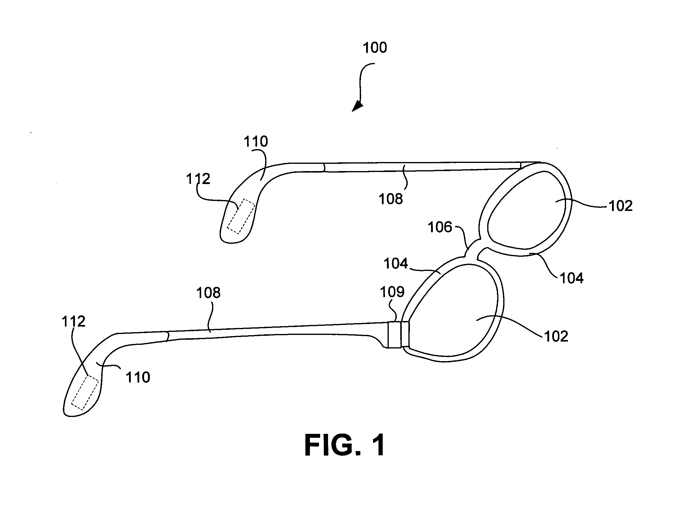
[0046]The invention pertains to techniques for providing eyewear with electrical components. The electrical components can provide electrical technology to eyewear (e.g., eyeglasses) without having to substantially compromise aesthetic design principles of the eyewear. Often, the electrical components can be attached to the eyewear as an after-market enhancement. The electrical components can operate independently or together with other electrical components provided elsewhere. Apparatus can also be provided to present after-market electrical components.

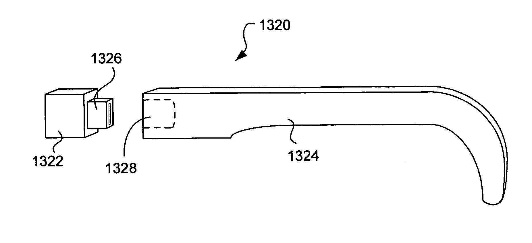
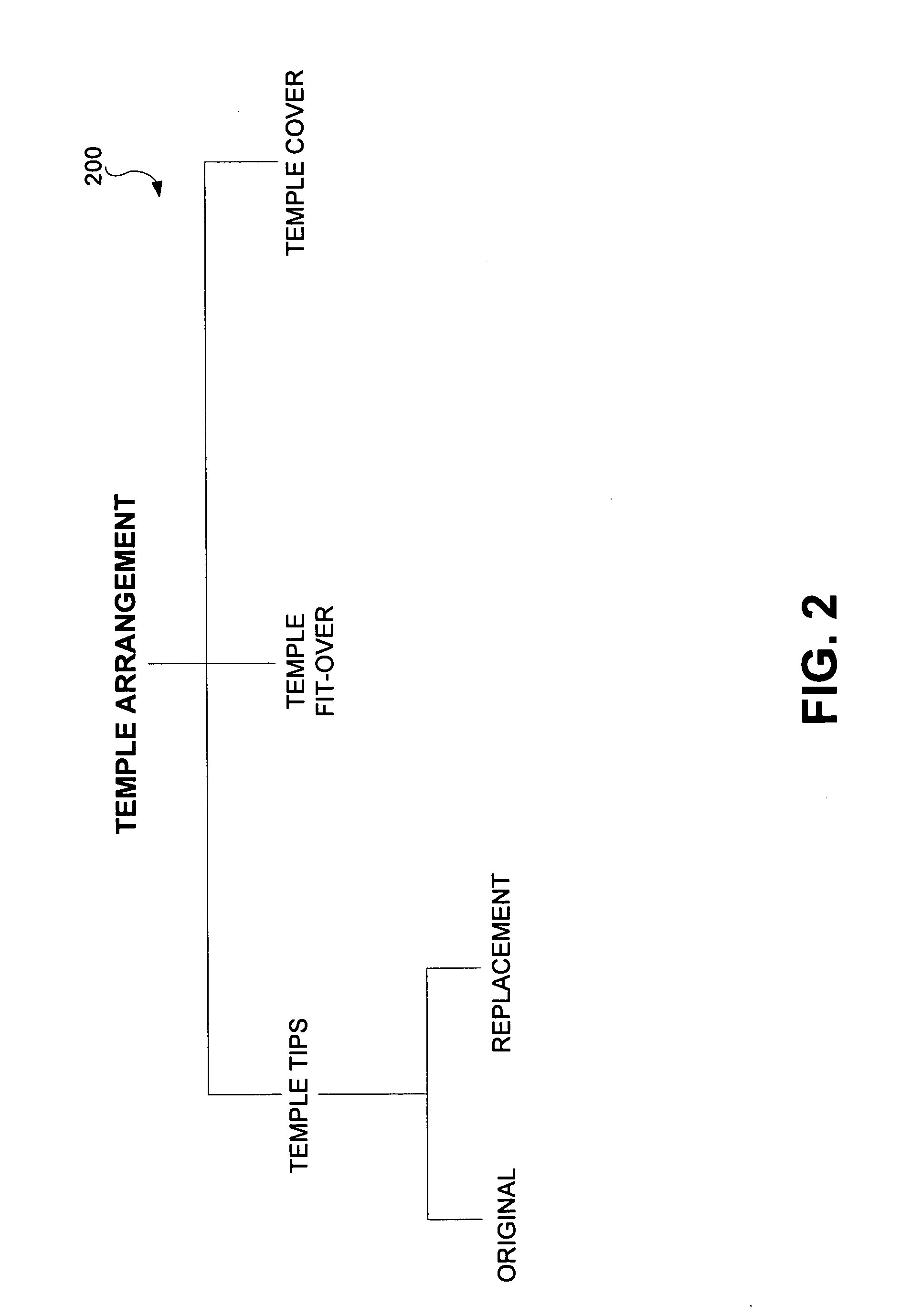
[0047]One aspect of the invention relates to temple arrangements for use with eyeglasses. According to this aspect, a temple arrangement includes one or more electrical components. The one or more electrical components are attached to or at least partially embedded in the temple arrangement.

[0048]Another aspect of the invention relates to a temple adapter for use with eyeglasses. According to this aspect, a temple adapter includes on...


PUM


Abstract

Techniques for providing eyewear with electrical components are disclosed. The electrical components can provide electrical technology to eyewear without having to substantially compromise aesthetic design principles of the eyewear. The electrical components can be partially or completely internal to eyewear. The electrical components can also be attached to the eyewear as an after-market enhancement. The electrical components can operate independently or together with other electrical components provided elsewhere. Apparatus for presenting after-market electrical components are also disclosed.

Description

CROSS-REFERENCE TO RELATED APPLICATIONS[0001]This application is a continuation-in-part of U.S. patent application Ser. No. 12 / 462,286, filed Jul. 31, 2009, and entitled “EYEWEAR SUPPORTING ELECTRICAL COMPONENTS AND APPARATUS THEREFOR” which is hereby incorporated herein by reference, which in turn is a continuation of U.S. patent application Ser. No. 11 / 580,222, filed Oct. 11, 2006, and entitled “EYEWEAR SUPPORTING AFTER-MARKET ELECTRICAL COMPONENTS” which is hereby incorporated herein by reference, which in turn is a continuation-in-part of U.S. patent application Ser. No. 11 / 183,269, filed Jul. 15, 2005, and entitled “EYEGLASSES SUPPORTING AFTER MARKET ELECTRICAL COMPONENTS,” which is hereby incorporated herein by reference, which in turn is a continuation-in-part of U.S. patent application Ser. No. 10 / 964,011, filed Oct. 12, 2004, and entitled “TETHERED ELECTRICAL COMPONENTS FOR EYEGLASSES,” which is hereby incorporated herein by reference, which in turn claims priority to each ...

Claims


Application Information

Patent Timeline
IPC IPC(8): G02C11/00G02C5/14
CPCG02C5/143G02C11/10G02C2200/08G02C11/06G02C5/146F21V33/0004F21W2111/10F21Y2115/10H02J7/00H02J7/0045
Inventor HOWELL, THOMAS A.CHAO, DAVIDTHOMAS, C. DOUGLASSTONG, PETER P.
Owner INGENIOSPEC
Why Eureka
Try Eureka