Insertion under read shield for improved read gap actuation in dynamic flying height

a dynamic flying height and insertion layer technology, applied in the field of insertion of nonmagnetic layers, can solve the problems of increasing the hysteresis rejection rate during quasi-static testing, putting a greater limit on the achievable spacing of the reader, and reducing the efficiency of the insertion of the read gap (rg)

Active Publication Date: 2010-12-09
HEADWAY TECH INC
View PDF11 Cites 43 Cited by
  • Summary
  • Abstract
  • Description
  • Claims
  • Application Information

AI Technical Summary

Benefits of technology

[0013]One objective of the present invention is to provide a read head configuration that will enable a more efficient read gap (RG) actuation such that a larger RG protrusion is achieved at the same power level compared with prior art read head structures.
[0014]Another objective of the present invention is to provide a read head configuration according to the first objective without exposing any metal layer at the ABS that could lead to a corrosion concern.
[0016]The insertion layer below the S1 shield is non-magnetic so as not to change the preferred S1 thickness and thereby avoid having an adverse magnetic effect as discussed previously regarding the consequences of a thicker S1 shield. The high CTE enhances the RG protrusion (at the same power into the heater element) which is equivalent to higher RG protrusion efficiency. Preferably, the insertion layer has high thermal conductivity in order to act as a superior heat sink to enable improved write current (Iw) driven protrusion. The volume of the non-magnetic insertion layer is limited so that the heat sink capacity does not reduce excessively the dynamic fly heating (DFH) temperature rise compared to when no non-magnetic insertion layer is present.

Problems solved by technology

A lower gamma ratio means the writer protrusion rate is much higher than the reader protrusion rate, and could potentially put a greater limit to achievable reader spacing.
With the increased imbalance of the S1 and S2A thickness resulting from a thicker S1, certain drawbacks in magnetic characteristics associated with the read shield thickness ratio create undesirable transfer curves for the reader.
One drawback is an increased hysteresis reject rate during quasi-static (QST) testing.

Method used


Image

  • Insertion under read shield for improved read gap actuation in dynamic flying height
  • Insertion under read shield for improved read gap actuation in dynamic flying height
  • Insertion under read shield for improved read gap actuation in dynamic flying height

Examples


Embodiment Construction

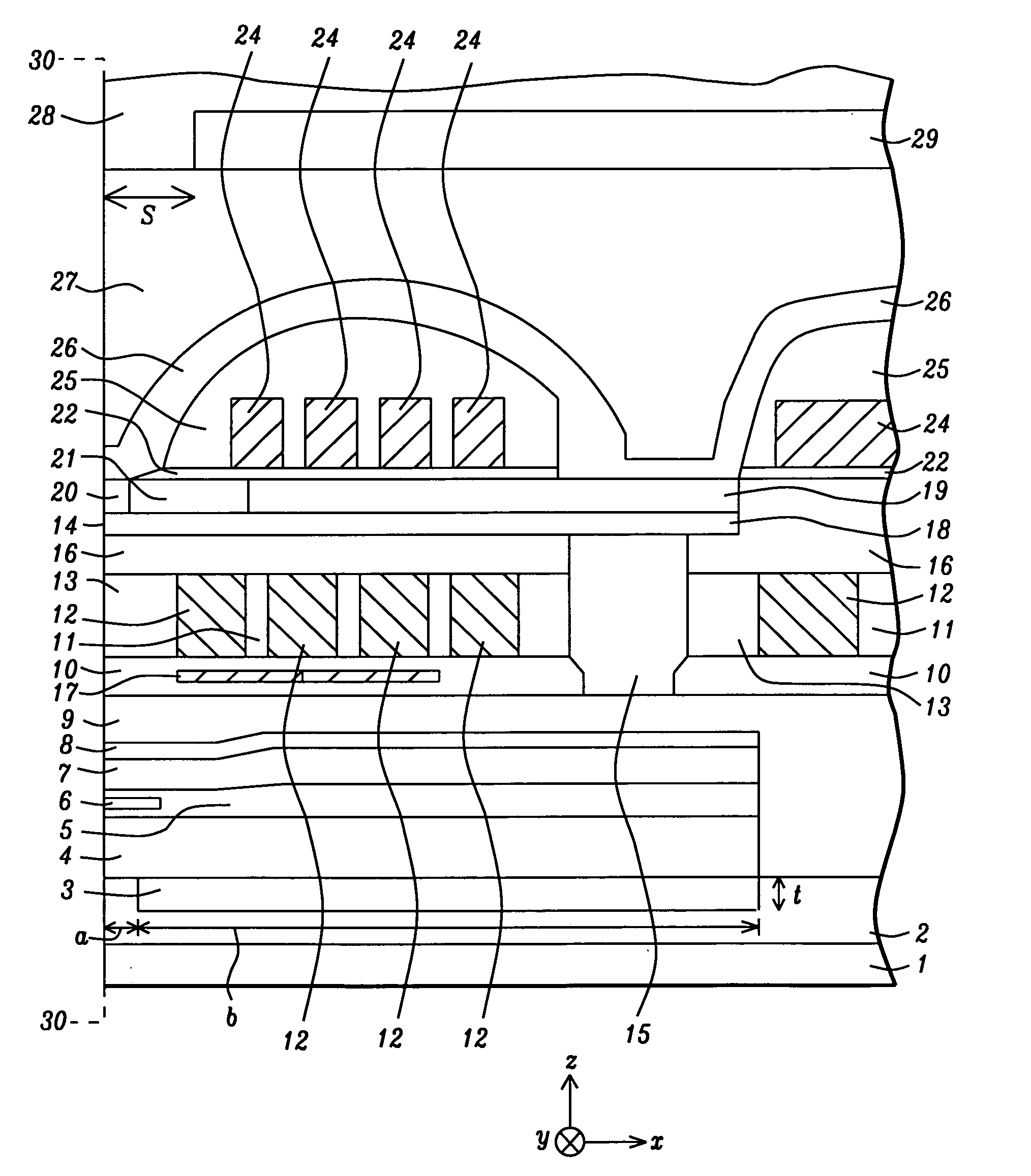
[0025]The present invention relates to a non-magnetic insertion layer that is formed in a read head on an opposite side of the S1 shield with respect to the sensor element and a method for making the same. Although a read / write head is depicted with an overcoat layer and a SiC cover layer in the exemplary embodiments, the present invention encompasses other recording head configurations as appreciated by those skilled in the art. The drawings are provided by way of example and are not intended to limit the scope of the invention.

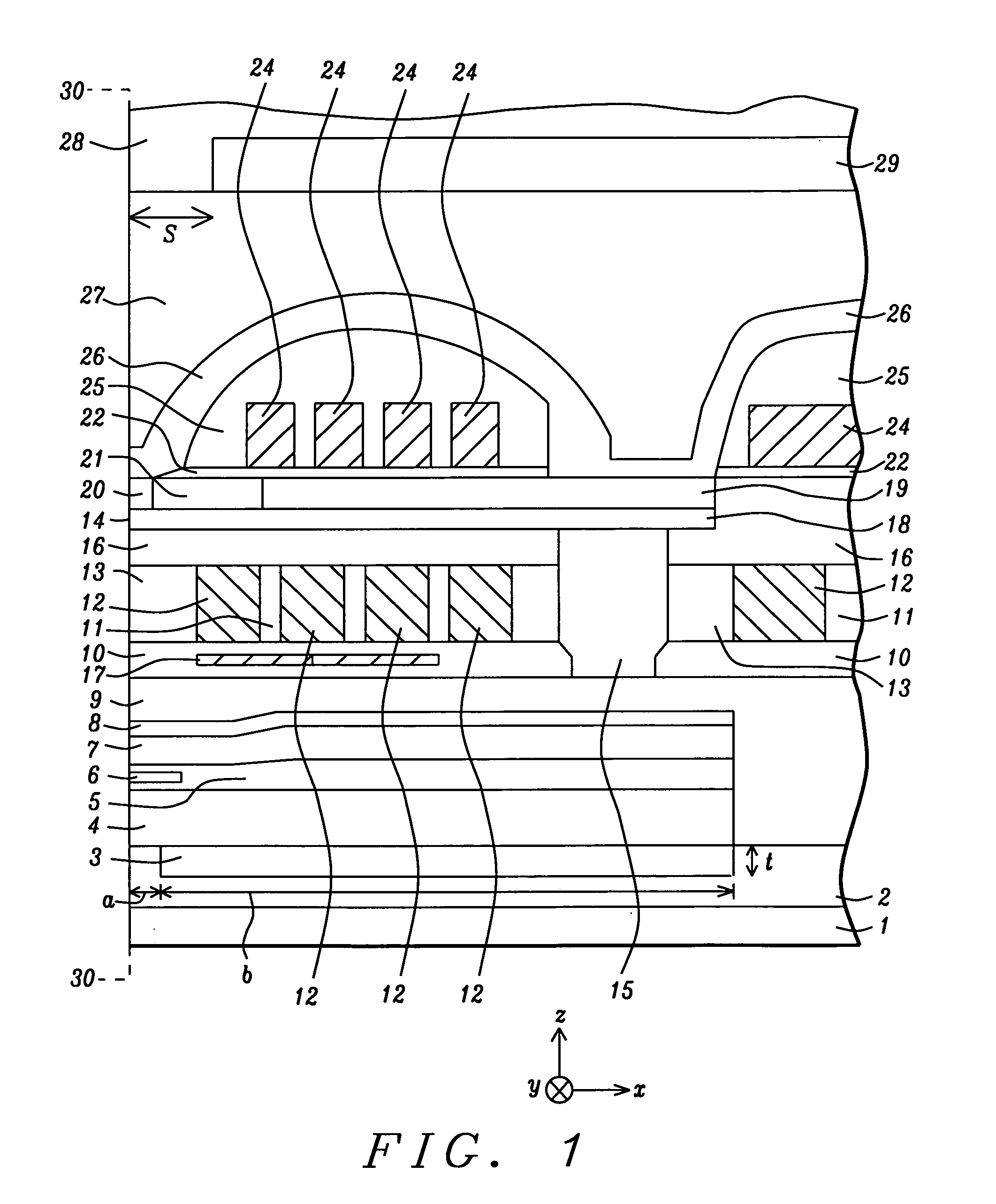
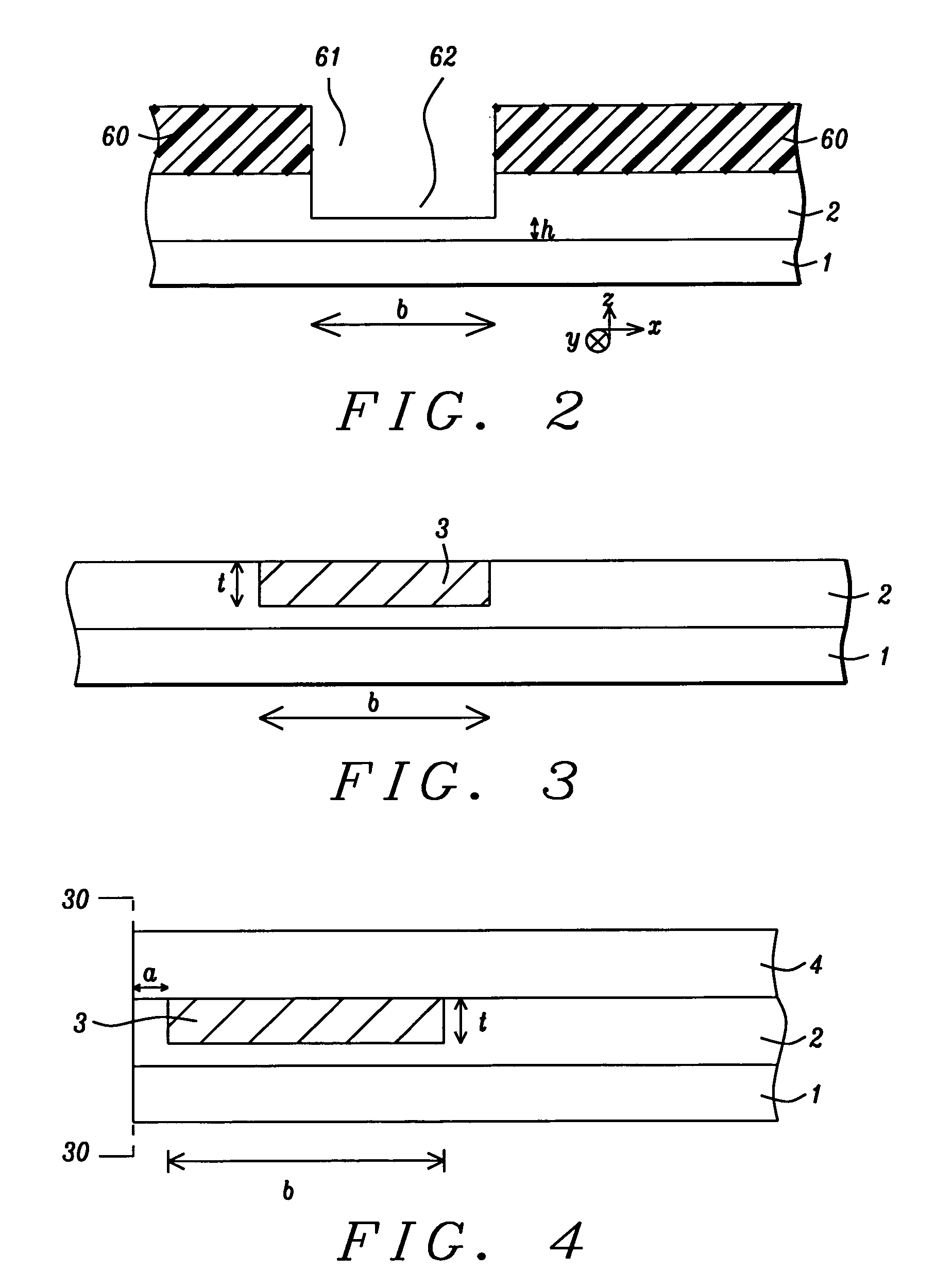
[0026]Referring to FIG. 1, one embodiment of a recording head of the present invention is depicted in a cross-sectional view from a plane orthogonal to an air bearing surface (ABS) 30-30. The read / write head is formed on a substrate 1 that may be comprised of AlTiC (alumina+TiC). The substrate 1 is typically part of a slider (not shown) formed in an array of sliders on a wafer. After the read / write head is completed, the wafer is sliced to form rows of slide...


PUM

PropertyMeasurementUnit
lengthaaaaaaaaaa
lengthaaaaaaaaaa
thicknessaaaaaaaaaa

Abstract

A read / write head is disclosed wherein a non-magnetic layer made of a metal is inserted in the read head on a side opposite to the S1 shield with respect to the sensor. The non-magnetic layer is preferably Cu and is recessed from the ABS to prevent corrosion. A preferred design has a 1 to 5 micron thick non-magnetic insertion layer that extends a distance of 3 to 100 microns along a plane that is perpendicular to the ABS. RG efficiency is enhanced significantly and RG gamma ratio is improved to 1.0 so that a smaller difference in RG, WG, and min-fly point can be achieved at touchdown detection and in normal read / write operations. These results lead to an optimal dynamic performance for a given spacing target and enhanced read gap protrusion at a given heater power. S1 / S2A thickness can be independently optimized for magnetic performance consideration only.

Description

RELATED PATENT APPLICATION[0001]This application is related to the following: Docket # HT07-043, Ser. No. 12 / 080,276, filing date Apr. 2, 2008; assigned to a common assignee, and herein incorporated by reference in its entirety.FIELD OF THE INVENTION[0002]The invention relates to the insertion of a non-magnetic layer with a high coefficient of thermal expansion (CTE) and high thermal conductivity below the first shield (S1) layer in a read head to enhance read gap (RG) protrusion at the same power, provide a better RG gamma parameter, and serve as a superior heat sink for improved write current (Iw) driven protrusion.BACKGROUND OF THE INVENTION[0003]Perpendicular recording has been developed in part to achieve higher recording density than is realized with longitudinal recording devices. A PMR write head typically has a main pole layer with a small surface area at an air bearing surface (ABS) and coils that conduct a current and generate a magnetic flux in the main pole that exits t...

Claims


Application Information

Patent Timeline
Patent Type & Authority Applications(United States)
IPC IPC(8): G11B5/10
CPCG11B5/1278G11B5/3116Y10T428/1193G11B5/6005G11B5/6064G11B5/3133
Inventor WU, YANLIU, KOWANG
Owner HEADWAY TECH INC
Why Eureka
Try Eureka