Fluid Disc Pump

a disc pump and fluid technology, applied in the direction of flexible member pumps, machines/engines, positive displacement liquid engines, etc., can solve the problems of reduced useful work done by the fluid actuator, reduced pump efficiency, and low amplitude acoustic resonance in the disc-shaped cavity, so as to reduce the dampening of the displacement oscillation, and mitigate any reduction of the pressure oscillation

Active Publication Date: 2010-12-09
TTP VENTUS LTD
View PDF6 Cites 56 Cited by
  • Summary
  • Abstract
  • Description
  • Claims
  • Application Information

AI Technical Summary

Benefits of technology

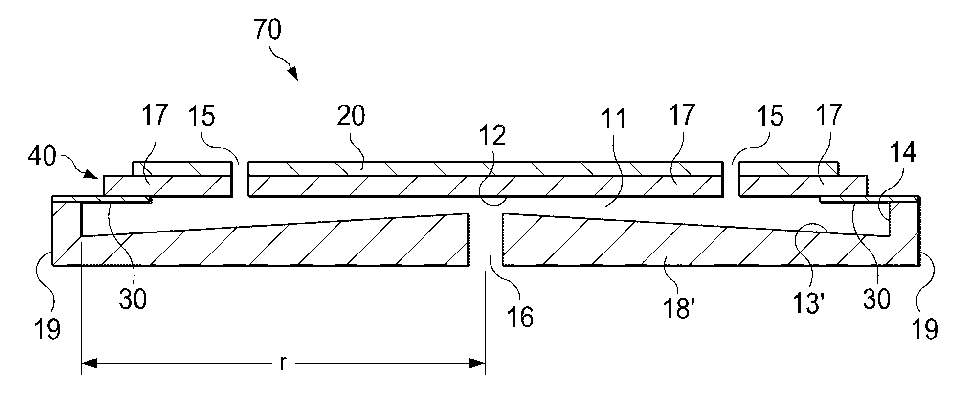
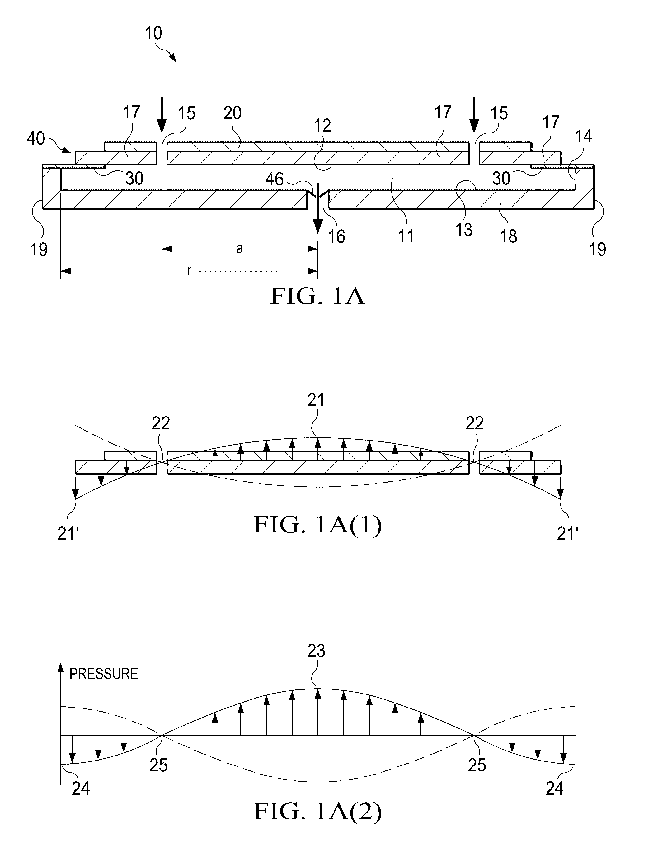
[0007]According to one embodiment of the invention, the actuator of the pump described above causes an oscillatory motion of the driven end wall (“displacement oscillations”) in a direction substantially perpendicular to the end wall or substantially parallel to the longitudinal axis of the cylindrical cavity, referred to hereinafter as “axial oscillations” of the driven end wall within the cavity. The axial oscillations of the driven end wall generate substantially proportional “pressure oscillations” of fluid within the cavity creating a radial pressure distribution approximating that of a Bessel function of the first kind as described in the '487 Application which is incorporated by reference herein, such oscillations referred to hereinafter as “radial oscillations” of the fluid pressure within the cavity. A portion of the driven end wall between the actuator and the side wall provides an interface with the side wall of the pump that decreases dampening of the displacement oscillations to mitigate any reduction of the pressure oscillations within the cavity, that portion being referred to hereinafter as an “isolator.” The illustrative embodiments of the isolator are operatively associated with the peripheral portion of the driven end wall to reduce dampening of the displacement oscillations.
[0008]According to another embodiment of the invention, a pump comprises a pump body having a substantially cylindrical shape defining a cavity formed by a side wall closed at both ends by substantially circular end walls, at least one of the end walls being a driven end wall having a central portion and a peripheral portion adjacent the side wall, wherein the cavity contains a fluid when in use. The pump further comprises an actuator operatively associated with the central portion of the driven end wall to cause an oscillatory motion of the driven end wall in a direction substantially perpendicular thereto with a maximum amplitude at about the centre of the driven end wall, thereby generating displacement oscillations of the driven end wall when in use. The pump further comprises an isolator operatively associated with the peripheral portion of the driven end wall to reduce dampening of the displacement oscillations caused by the end wall's connection to the side wall of the cavity. The pump further comprises a first aperture disposed at about the centre of one of the end walls, and a second aperture disposed at any other location in the pump body, whereby the displacement oscillations generate radial oscillations of fluid pressure within the cavity of said pump body causing fluid flow through said apertures.

Problems solved by technology

However, high amplitude acoustic resonance has not been employed within disc-shaped cavities in which radial pressure oscillations are excited until recently.
Thus, the useful work done by the actuator on the fluid is reduced and the pump becomes less efficient.

Method used


Image

  • Fluid Disc Pump
  • Fluid Disc Pump
  • Fluid Disc Pump

Examples


first embodiment

[0054]Referring more specifically to FIGS. 7A and 7B, additional embodiments of the flexible membrane 31 having structural features that enhance the stretch-ability of the flexible member 31 to facilitate the radial motion of the actuator 40 are shown. Referring more specifically to FIG. 7A, a structurally modified flexible membrane 32 is shown that includes an annular concertina portion 33 extending between the actuator 40 and the side wall 14. The concertina portion 33 comprises annular bends in the flexible membrane 32 appearing as waves in FIG. 7A that expand and contract with the motion of the actuator 40 like an accordion. The concertina portion 33 of the flexible membrane 32 effectively reduces the radial stiffness of the flexible membrane 32 thereby enhancing the stretch-ability of the flexible membrane 32 and enabling the actuator 40 to expand and contract more easily in a radial direction.

second embodiment

[0055]Referring more specifically to FIG. 7B, a structurally modified flexible membrane 34 is shown that includes annular, semi-circular grooves 35 staggered on each side of the flexible membrane 34 between the actuator 40 and the side wall 14. The annular grooves 35 of the flexible membrane 34 may be formed by chemical etching, grinding, or any similar processes, or may be formed by laminations. The annular grooves 35 of the flexible membrane 34 effectively reduce the radial stiffness of the flexible membrane 34 thereby enhancing the stretch-ability of the flexible membrane 34 to facilitate the expansion and contraction of the actuator 40 in the radial direction. Note that the structures shown in FIGS. 7A and 7B and similar structures may also beneficially reduce the force required to bend the isolators 32, 34 in the axial direction.

[0056]Although the isolator 30 and flexible membranes 31, 32 and 34 shown in the previous figures are ring-shaped components extending between the side...


PUM


Abstract

A pump having a substantially cylindrical shape and defining a cavity formed by a side wall closed at both ends by end walls wherein the cavity contains a fluid is disclosed. The pump further comprises an actuator operatively associated with at least one of the end walls to cause an oscillatory motion of the driven end wall to generate displacement oscillations of the driven end wall within the cavity. The pump further comprises an isolator operatively associated with a peripheral portion of the driven end wall to reduce dampening of the displacement oscillations.

Description

BACKGROUND OF THE INVENTION[0001]1. Field of the Invention[0002]The illustrative embodiments of the invention relate generally to a pump for fluid and, more specifically, to a pump in which the pumping cavity is substantially a disc-shaped, cylindrical cavity having substantially circular end walls and a side wall.[0003]2. Description of Related Art[0004]The generation of high amplitude pressure oscillations in closed cavities has received significant attention in the fields of thermo-acoustics and pump type compressors. Recent developments in non-linear acoustics have allowed the generation of pressure waves with higher amplitudes than previously thought possible.[0005]It is known to use acoustic resonance to achieve fluid pumping from defined inlets and outlets. This can be achieved using a cylindrical cavity with an acoustic driver at one end, which drives an acoustic standing wave. In such a cylindrical cavity, the acoustic pressure wave has limited amplitude. Varying cross-sect...

Claims


Application Information

Patent Timeline
Patent Type & Authority Applications(United States)
IPC IPC(8): F04B19/00
CPCF04F7/00F04B43/04
Inventor JANSE VAN RENSBURG, RICHARD
Owner TTP VENTUS LTD
Why Eureka
Try Eureka