Supercharge Your Innovation With Domain-Expert AI Agents!

CAD apparatus and check support apparatus

a support apparatus and cad technology, applied in the field of circuit design, can solve the problems of not improving the efficiency of designing the printed circuit board itself, the name of the pin of the connector cannot be freely set, and conventional technologies are not applicabl

Inactive Publication Date: 2010-12-09
FUJITSU LTD
View PDF20 Cites 3 Cited by
  • Summary
  • Abstract
  • Description
  • Claims
  • Application Information

AI Technical Summary

Problems solved by technology

The conventional technologies improve efficiency of the checking operation performed after design of printed circuit boards to be connected via connectors is once completed; however, these technologies do not improve efficiency of designing a printed circuit board itself.
However, it is often the case that actual design work is performed using connector information that have already been registered, and names of pins of connectors cannot be freely set.
In this case, the conventional technologies are not applicable that require assignment of the same name to corresponding connector pins.

Method used


Image

  • CAD apparatus and check support apparatus
  • CAD apparatus and check support apparatus
  • CAD apparatus and check support apparatus

Examples


Embodiment Construction

[0049]Exemplary embodiments of the present art are explained in detail below with reference to the accompanying drawings.

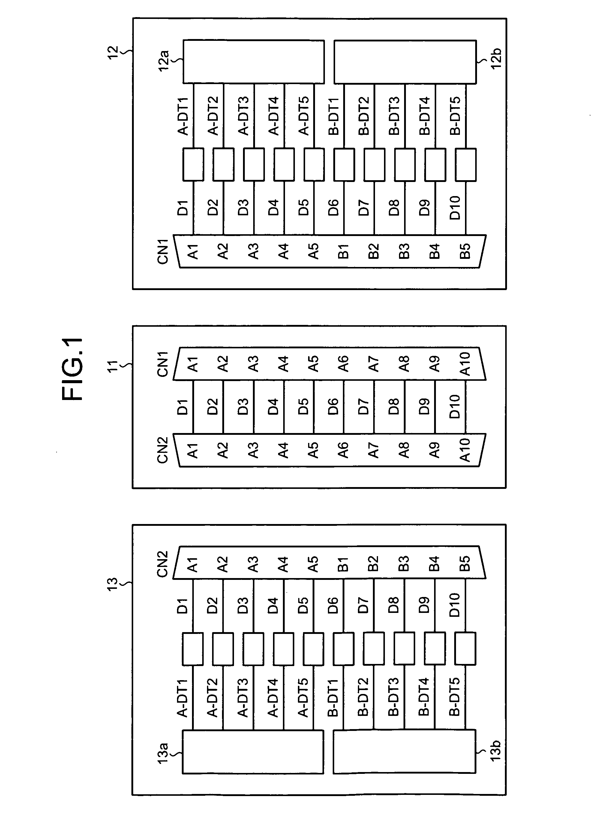
[0050]An embodiment of the present art is explained with a printed circuit board (PCB) 11 shown in FIG. 1 as an example. The printed circuit board 11 is a back wiring board (BWB) for connecting printed circuit boards 12 and 13 with each other, and includes connectors CN1 and CN2. The connectors CN1 and CN2 each include 10 pins A1 to A10. Among the pins A1 to A10 of the connectors CN1 and CN2, respective sets of pins having the same pin name are connected via signal lines with net names D1 to D10.

[0051]The printed circuit board 12 has a predetermined function, and includes a connector CN1 to be connected to the connector CN1 of the printed circuit board 11. The connector CN1 includes 10 pins A1 to A5 and B1 to B5.

[0052]The pins A1 to A5 are connected to an integrated circuit (IC) 12a via a part such as a resistor. Signal lines with net names D1 to D5 connects the p...


PUM


Abstract

In a computer aided design (CAD) apparatus, an association-data acquiring unit acquires association data that defines an association between pins of a first connector and those of a second connector to be connected to the first connector, and an assignment of signals to the pins. A part-information acquiring unit acquires information including a symbol of the first connector. A layout-condition acquiring unit acquires a layout condition to lay out the symbol of the first connector on a circuit diagram. A circuit diagram creating / updating unit lays out the symbol of the first connector on the circuit diagram based on the layout condition, and adds a net name indicating a signal assigned to each of the pins to the symbol.

Description

CROSS-REFERENCE TO RELATED APPLICATIONS[0001]This application is a divisional of U.S. application Ser. No. 12 / 000,098, filed on Dec. 7, 2007, which is a continuation-in-part of prior U.S. application Ser. No. 11 / 902,940, filed on Sep. 26, 2007; Ser. No. 11 / 905,108, filed on Sep. 27, 2007; Ser. No. 11 / 905,315, filed on Sep. 28, 2007; and Ser. No. 11 / 980,396, filed on Oct. 31, 2007; and it being further noted that priority is based upon the prior Japanese Patent Application Nos. 2006-330500, filed on Dec. 7, 2006; 2006-330501, filed on Dec. 7, 2006; 2006-330502, filed on Dec. 7, 2006; 2006-330503, filed on Dec. 7, 2006; 2007-307150, filed on Nov. 28, 2007; 2007-307151, filed on Nov. 28, 2007; 2007-307152, filed on Nov. 28, 2007; and 2007-307153, filed on Nov. 28, 2007.BACKGROUND[0002]1. Field[0003]The present art relates to a technology for circuit design.[0004]2. Description of the Related Art[0005]An electronic circuit that controls an information processing apparatus, a communicati...

Claims


Application Information

Patent Timeline
Patent Type & Authority Applications(United States)
IPC IPC(8): G06F17/50
CPCG06F17/5045G06F2217/40G06F2217/36G06F30/30G06F2113/16G06F2113/18
Inventor KUMAGAI, YOSHITOMO
Owner FUJITSU LTD
Features
  • R&D
  • Intellectual Property
  • Life Sciences
  • Materials
  • Tech Scout
  • Unparalleled Data Quality
  • Higher Quality Content
  • 60% Fewer Hallucinations
Learn More