Method and apparatus for configuring systems

a technology of system configuration and method, applied in the field of computer-based system configuration, can solve the problems of not addressing the actual need for computer-based tools, complex task of configuring a system, and needing computer-based assistan

Inactive Publication Date: 2006-05-09
VERSATA DEV GROUP
View PDF9 Cites 100 Cited by
  • Summary
  • Abstract
  • Description
  • Claims
  • Application Information

AI Technical Summary

Benefits of technology

[0028]The present invention employs a generative approach for configuring systems such that a system may be configured based on component or resource requests, or input in the form of need. The present invention provides a constraint-based configuration system using a functional hierarchy that comprehends hierarchical and non-hierarchical structure, and associated constra

Problems solved by technology

As system specifications become more customized and varied, configuration alternatives increase and the task of configuring a system becomes more complex.
This increased complexity has resulted in a need for computer-based assistance with the configuration process.
They do not address the actual need for computer-based tools prior to the order expansion.
That is, they do not address the actual generation of a system configuration based on needs and/or request input.
While the total power available in the two cabinets may be sufficient for all of the components to be placed in both of the cabinets, a component cannot be included in a cabinet if its inclusion would cause the cabinet's power supply to overload.
Therefore, it is difficult and time-consuming to maintain these rules.
For example, a hard disk drive cannot be added to the configuration unless a compatible storage device controller is available for use by the request storage device.
While existing constraint-based systems address some of the shortcomings of rule-based systems, they do not provide a complete configuration tool.
Thus, Bennett does not provide the capability to interactively configure a system by interactively se

Method used


Image

  • Method and apparatus for configuring systems
  • Method and apparatus for configuring systems
  • Method and apparatus for configuring systems

Examples


Embodiment Construction

[0055]A method and apparatus for configuring systems is described. In the following description, numerous specific details are set forth in order to provide a more thorough description of the present invention. It will be apparent, however, to one skilled in the art, that the present invention may be practiced without these specific details. In other instances, well-known features have not been described in detail so as not to obscure the invention.

[0056]The present invention provides a tool for configuring systems that has application to a wide range of domains including the following: computer hardware, computer software, computer networks, telecommunication systems (e.g., PBX and voice mail), copiers, medical imaging systems, vehicles (e.g., fire trucks and construction equipment), electronic control systems, buildings, modular furniture, manufacturing equipment, manufacturing systems, consumer electronic equipment, and electronic systems.

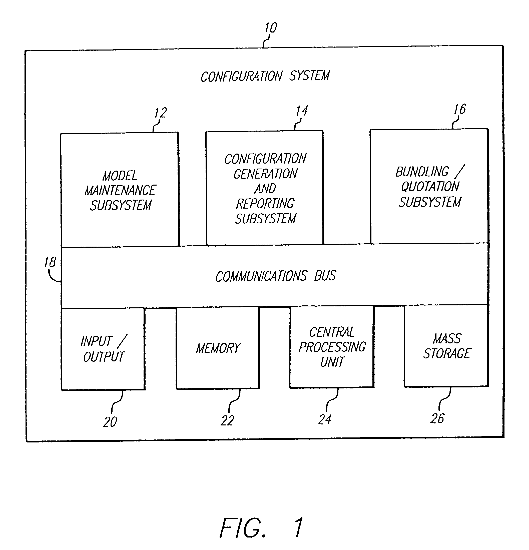
[0057]FIG. 1 is block diagram of the conf...


PUM


Abstract

The present invention employs a generative approach for configuring systems such that a system may be configured based on component or resource requests, or input in the form of need. The present invention provides a constraint-based configuration system using a structural model hierarchy. The structural aspects of the model provide the ability to define a model element as being contained in, or by, another model element. In addition, the structural model provides the ability to identify logical datatype and physical interconnections between elements and establish connections between elements. To configure a system, the present invention accepts input in the form of requests (e.g., component or resource) or needs, such as an expression of a need for a desktop computer system to be used in a CAD (i.e., computer-aided design) environment. Using this information, the present invention configures a system by identifying the resource and component needs, constraints imposed on or by the resources or components identified, and the structural aspects of the system.

Description

BACKGROUND OF THE INVENTION[0001]This appln. is a CON of Ser. No. 08 / 815,399 filed on Mar. 10, 1997 now U.S. Pat. No. 6,002,854.[0002]1. Field of the Invention[0003]This invention relates to the field of computer-based system configuration.[0004]2. Background Art[0005]Configuring a system refers to the process of selecting and connecting components to satisfy a particular need or request. If a system is based on a limited number of components, the process of configuring the system can be relatively straightforward. For example, the purchase of an automobile requires a salesperson to configure a system (automobile and assorted options) to satisfy a customer's request. After selecting from a plurality of models, the salesperson completes the transaction by selecting options to configure and price an automobile. The configuring of such a simple system can be accomplished with a pencil and paper.[0006]As system specifications become more customized and varied, configuration alternatives...

Claims


Application Information

Patent Timeline
IPC IPC(8): G06F15/177G06F17/50
CPCG06F17/5095G06F2217/78G06F30/15G06F2119/06
Inventor LYNCH, JOHNFRANKE, DAVID
Owner VERSATA DEV GROUP
Why Eureka
Try Eureka