Design verification for asymmetric phase shift mask layouts

a technology of asymmetric phase shift mask and design verification, which is applied in the direction of photomechanical treatment originals, instruments, photo-taking processes, etc., can solve the problems of limited exposure system resolution and mask defects

Inactive Publication Date: 2001-02-06
IBM CORP
View PDF2 Cites 108 Cited by
  • Summary
  • Abstract
  • Description
  • Claims
  • Application Information

AI Technical Summary

Problems solved by technology

This resolution of an exposure system is limited by the contrast of the projected image; that is, the intensity difference between adjacent light and dark features.
Design errors can cause defecti...

Method used


Image

  • Design verification for asymmetric phase shift mask layouts
  • Design verification for asymmetric phase shift mask layouts
  • Design verification for asymmetric phase shift mask layouts

Examples


Embodiment Construction

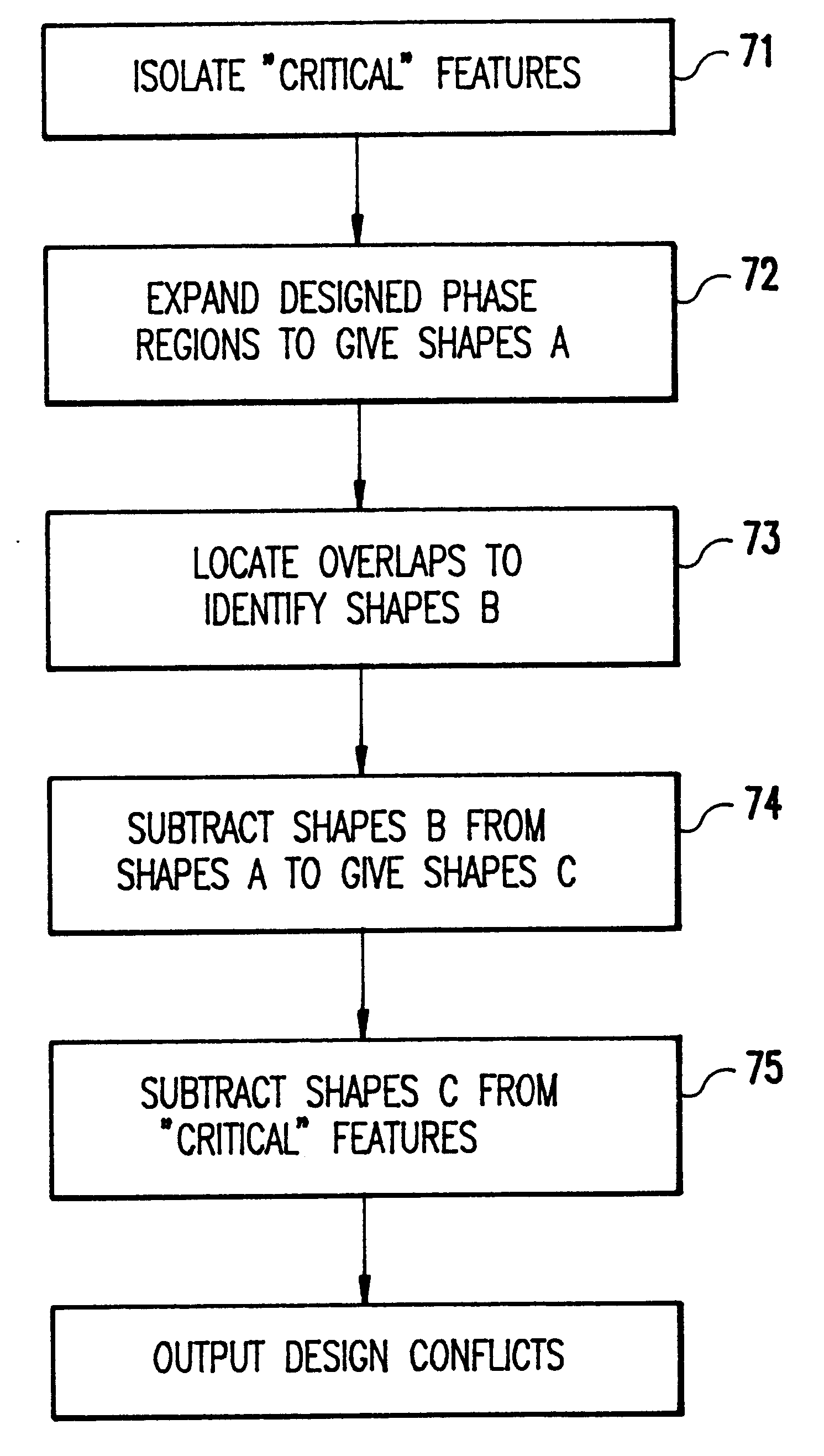
The PSM design algorithm disclosed in application Ser. No. 08 / 290,625 allows binary mask layouts to be converted to phase edge.PSM layouts on a CAD system supporting basic Boolean operations. The present invention addresses the issue of verifying a phase edge PSM layout, generated by the routine disclosed in application Ser. No. 08 / 290,625 or any other design tool. The phase edge PSM design checker according to the invention can be implemented in any CAD system supporting basic shape manipulation and Boolean operations. For example, the invention can be implemented in a CAD application, such as IBM's Hierarchical shapes processing engine "Niagara", running on a workstation, such as an IBM RISC / 6000 computer. It can also be implemented in other commercially available CAD systems, such as the CADENCE layout editor by Cadence Design Systems Inc., running on any supported workstation. It is also possible to include the PSM design verification as part of CAD design enhancement operations...


PUM


Abstract

A checking routine verifies a phase shifted mask (PSM) design based on fundamental principles of PSM and utilizing only basic shape manipulation functions and Boolean operations found in most computer aided design (CAD) systems. The design verification system checks complete chip designs for the two possible design errors that can cause defective masks by eliminating the phase transition; namely, placing a 180° phase region on both sides of a critical feature or completely omitting the phase region adjacent to certain critical features.

Description

1. Field of the InventionThe present invention generally relates to the manufacture of very large scale integrated (VLSI) circuit devices and, more particularly, to the resolution enhancement of photolithographic images through the use of phase shifted masks (PSMs).2. Background DescriptionManufacturing of semiconductor devices is dependent upon the accurate replication of computer aided design (CAD) generated patterns onto the surface of a device substrate. The replication process is typically performed using optical lithography followed by a variety of subtractive (etch), additive (deposition) and material modification (e.g., oxidations, ion implants, etc.) processes. Optical lithography patterning involves the illumination of a metallic coated quartz plate known as a photomask which contains a magnified image of the computer generated pattern etched into the metallic layer. This illuminated image is reduced in size and patterned into a photosensitive film on the device substrate....

Claims


Application Information

Patent Timeline
IPC IPC(8): G03F1/00G03F1/30
CPCG03F1/30
Inventor LIEBMANN, LARS WOLFGANG
Owner IBM CORP
Why Eureka
Try Eureka