Adjustable Pry Bar

a technology of adjustable prying bar and adjustable angle, which is applied in the direction of crowbars, lifting devices, anti-plastic agents, etc., can solve the problem that the angle between the prying bar and the handle cannot be randomly adjusted in different working spaces, and achieve the effect of easily adjusting the angle of the prying bar

Inactive Publication Date: 2010-12-16
FAN CHEN JUN
View PDF59 Cites 24 Cited by
  • Summary
  • Abstract
  • Description
  • Claims
  • Application Information

AI Technical Summary

Benefits of technology

[0006]The primary object of the present invention is to provide an adjustable pry bar which can adjust the angle of the prying block easily.

Problems solved by technology

Conventional pry bat are used in vehicle maintenance or mechanical repairs process, however an angle between the prying block and the handle can not be adjusted randomly in different working space.

Method used


Image

  • Adjustable Pry Bar
  • Adjustable Pry Bar
  • Adjustable Pry Bar

Examples


first embodiment

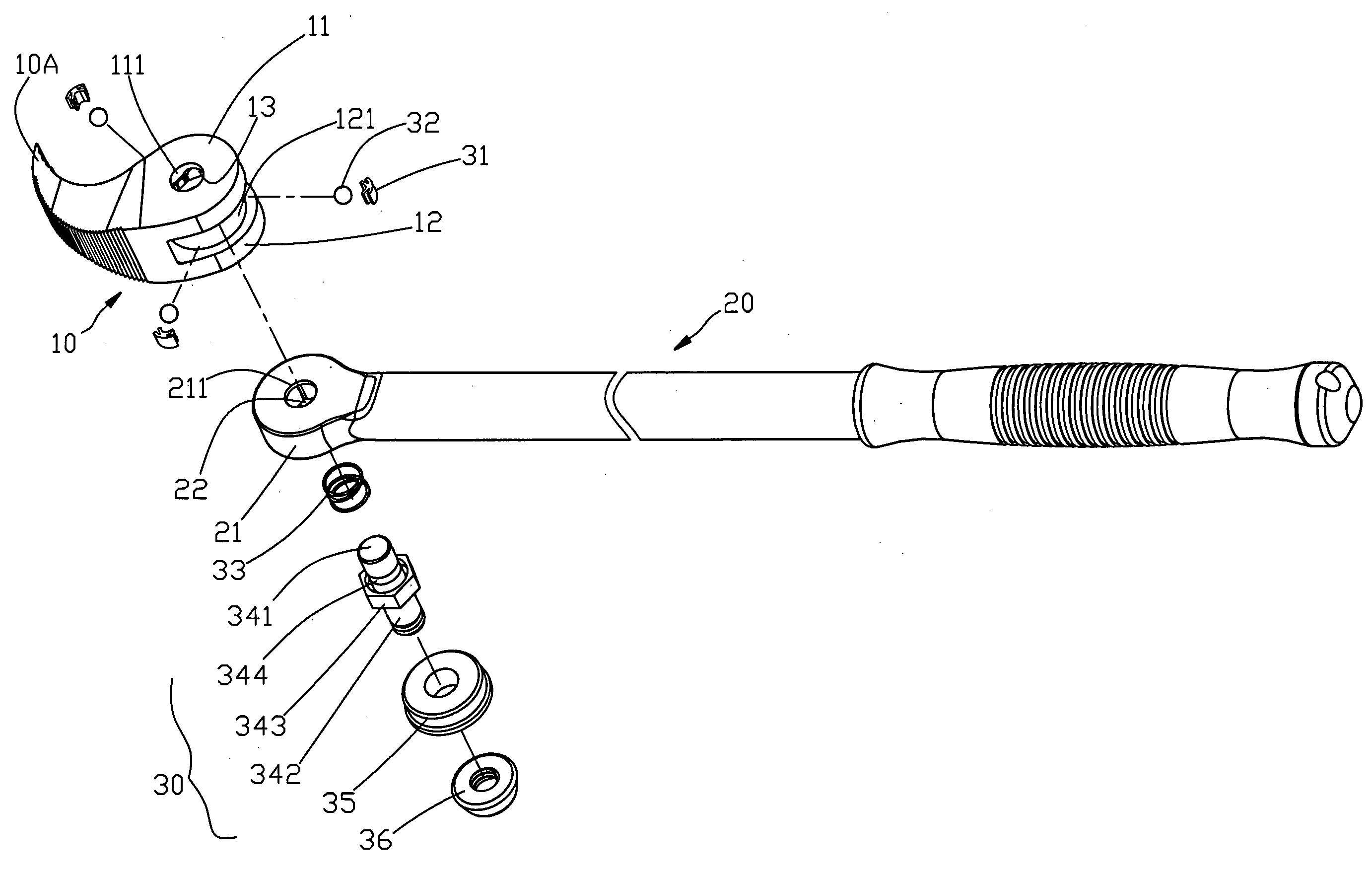
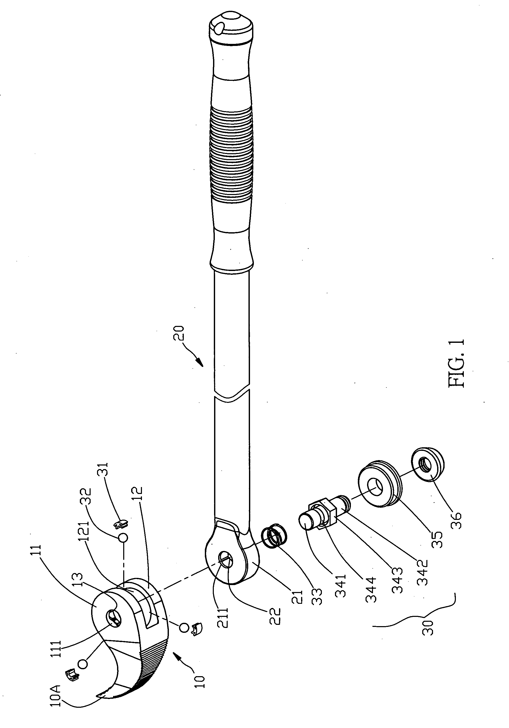
[0029]Referring to FIG. 1, an adjustable pry bar in accordance with the present invention comprises: a prying block 10, a handle 20, an adjusting mechanism 30, wherein

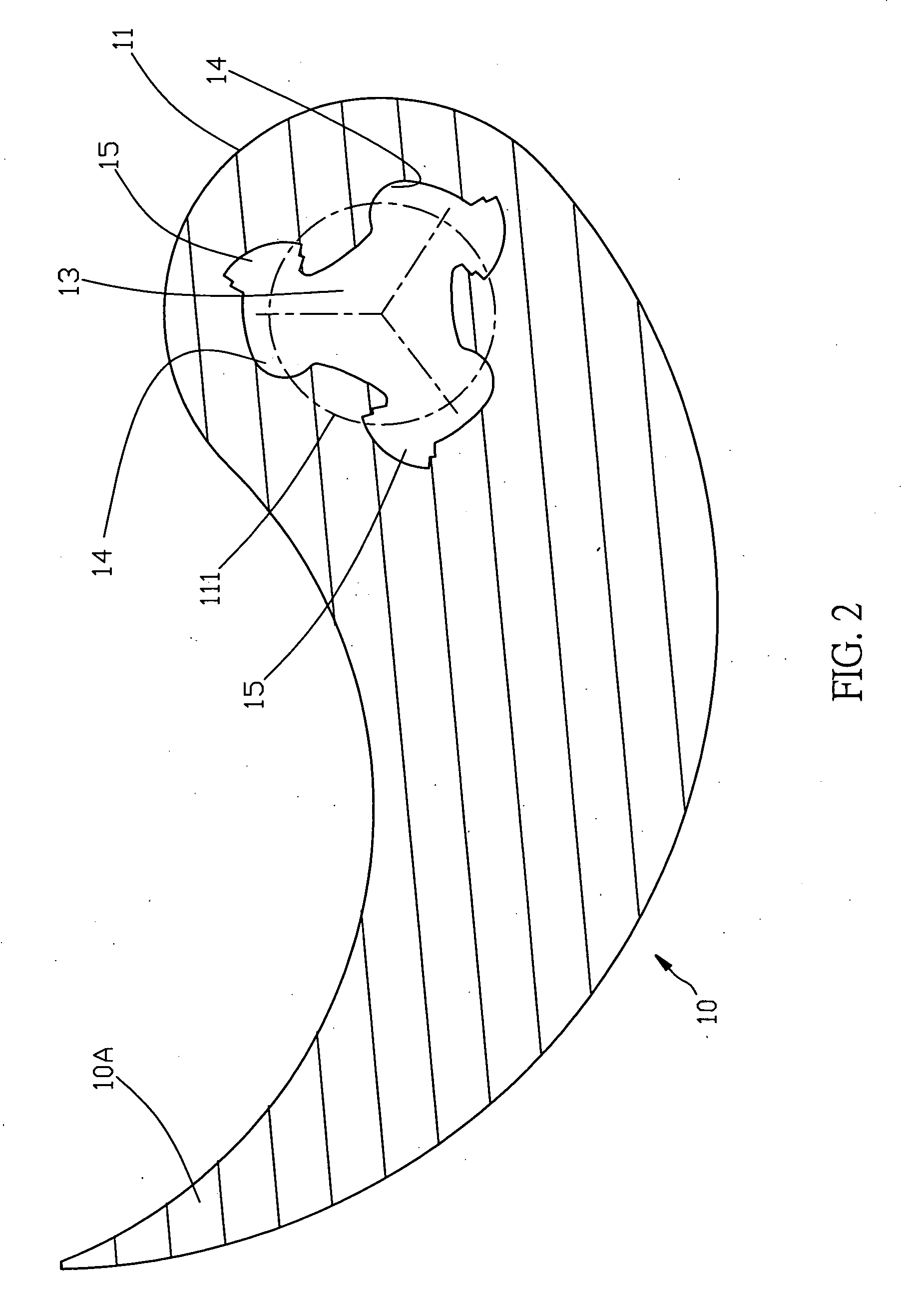
[0030]the prying block 10 is formed in an upward-extending tip shape and includes a hook 10A disposed on a front end thereof to pry and remove an object, and includes a first and a second side wings 11, 12 mounted on a rear end thereof and being parallel to each other, the first and the second side wings 11, 12 include a first and a second through holes 111, 112 fixed on central portions thereof respectively, the first side wing 11 includes a groove 13 arranged on an internal end surface thereof to communicate with the first through hole 111, the groove 13 includes three radially extending ends, each having a positioning portion 14 and a receiving chamber 15 proximate to the positioning portion 14;

[0031]the handle 20 as illustrated in FIGS. 1 and 4, includes a head end 21 defined on a front end thereof to be axially co...

second embodiment

[0038]With reference to FIG. 8, an adjustable pry bar in accordance with the present invention comprises a handle 20 including two screw bore 531 disposed on two sides of a distal end thereof individually to screw with a cone-shaped member 50, and a first hammer 51. An outer side of the head end 21 also screws with a second hammer 53. In operation, the second hammer 53 is disengaged from the head end 21, however as desiring to hammer an object, the second hammer 53 is screwed with and a screw bore 531 of the head end 21, and as desiring to pry something else, the cone-shaped member 50 is screwed into the screw bore 531 of the distal end of the handle 20, obtaining hammering and prying purposes.

third embodiment

[0039]Referring to FIGS. 9-11, an adjustable pry bar in accordance with the present invention comprises a handle 20A with a tip stem 60, the tip stem 60 includes outer threads 61 formed thereon so as to fit a sleeve 62, the sleeve 62 includes a cutout 621 disposed therein and having inner threads 623 arranged in the cutout 621 so that the tip stem 60 is inserted in the cutout 621 to be screwed with the sleeve 62 by ways of the outer and inner threads 61, 623. In operation, the sleeve 62 is disengaged from the tip stem 60 so that the tip stem 60 is used to knock and impact an object on a spot. As illustrated in FIG. 11, the handle 20A includes a hammer 53 and a cone-shaped member 50, both of which are screwed to the head end 2-1 individually.

[0040]While we have shown and described various embodiments in accordance with the present invention, it is clear to those skilled in the art that further embodiments may be made without departing from the scope of the present invention.


PUM


Abstract

An adjustable pry bar comprises a prying block used to pry and remove an object and including first and second side wings mounted on a rear end thereof and parallel to each other to clamp a head end of a handle, the first side wing including a groove to receive multiple balls and biasing members; an adjusting mechanism installed in a central aperture and a notch of the head end and including a plurality of biasing members and balls, a shaft member, and a control member, the biasing member being flexible to be pushed backward to abut against the balls, the shaft member including a first end for engagement with the balls, the first end including a recess arranged around an outer rim thereof, the shaft member also including a second end extending out of a second through hole of the second side wing to coupled with the control member.

Description

BACKGROUND OF THE INVENTION[0001]1. Field of the Invention[0002]The present invention relates to hand tool, and more particularly to an adjustable pry bar.[0003]2. Description of the Prior Art[0004]Conventional pry bat are used in vehicle maintenance or mechanical repairs process, however an angle between the prying block and the handle can not be adjusted randomly in different working space.[0005]The present invention has arisen to mitigate and / or obviate the afore-described disadvantages.SUMMARY OF THE INVENTION[0006]The primary object of the present invention is to provide an adjustable pry bar which can adjust the angle of the prying block easily.[0007]Another object of the present invention is to provide an adjustable pry bar which can be uses as a hammer as well.[0008]An adjustable pry bar according to the present invention comprises:[0009]a prying block including a hook disposed on a front end thereof to pry and remove an object, and including a first and a second side wings ...

Claims


Application Information

Patent Timeline
Patent Type & Authority Applications(United States)
IPC IPC(8): B66F15/00
CPCB25G3/38B66F15/00A61P35/00
Inventor FAN, CHEN JUN
Owner FAN CHEN JUN
Why Eureka
Try Eureka