

Ski binding and ski therefor
- Summary
- Abstract
- Description
- Claims
- Application Information
AI Technical Summary
Benefits of technology
Problems solved by technology
Method used
Image

Examples
Embodiment Construction
[0035]In the drawing figures, identical elements bear the same reference numerals. In the following description, the terms “upper,”“lower,”“high,”“low,”“horizontal,” and “vertical” are used with reference to the upright position of the skier.
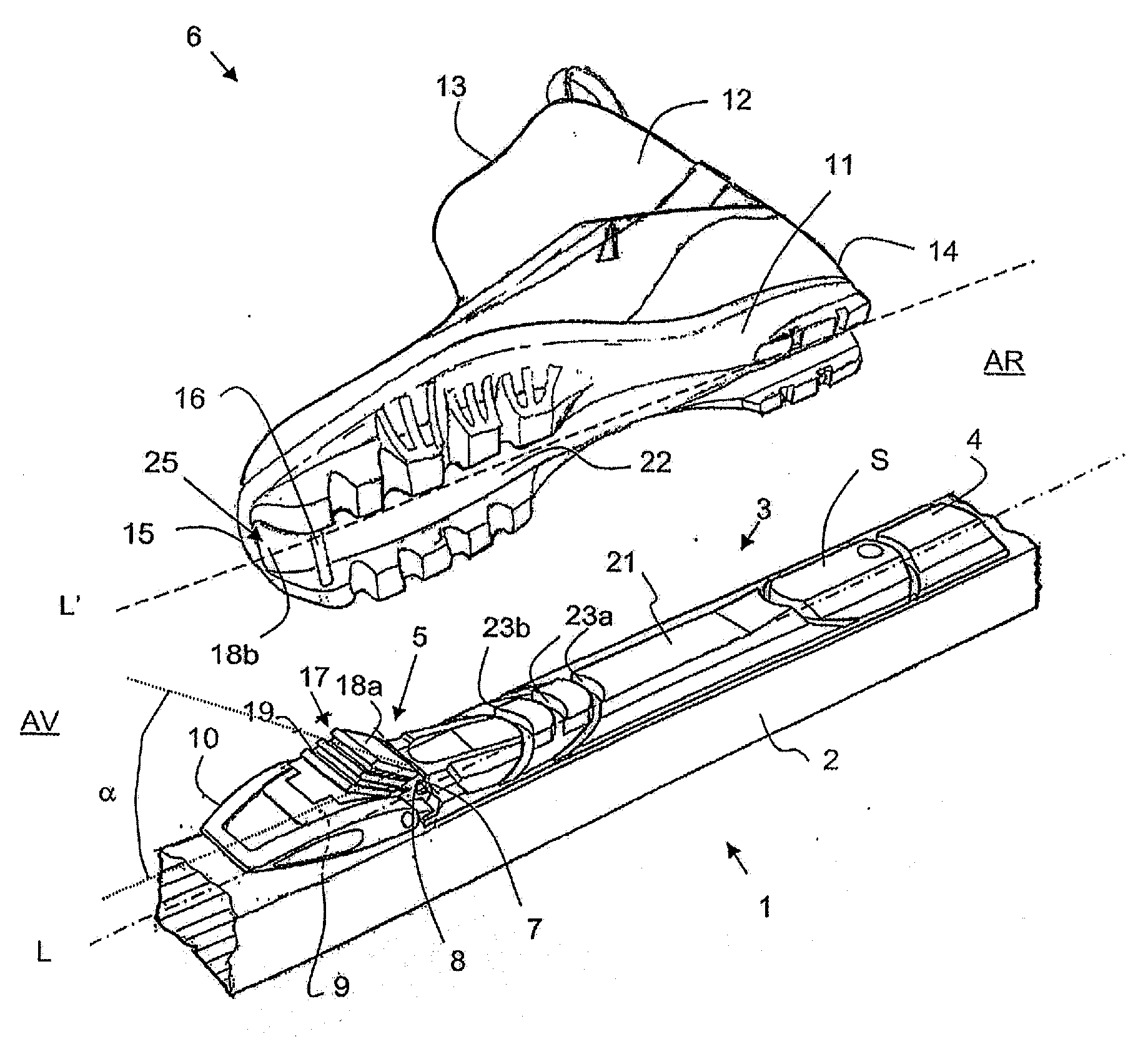
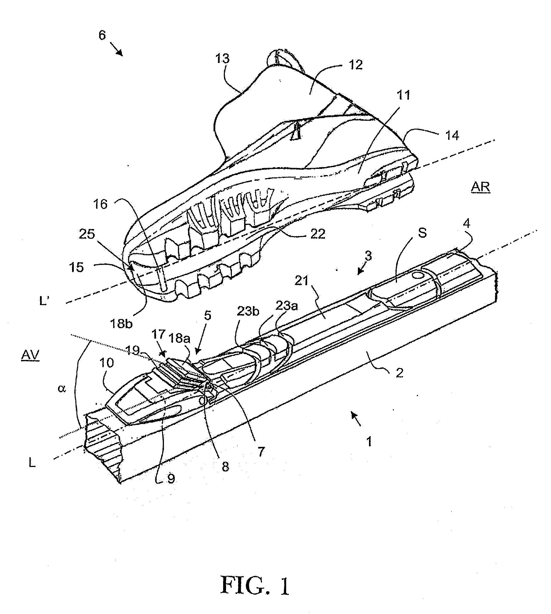
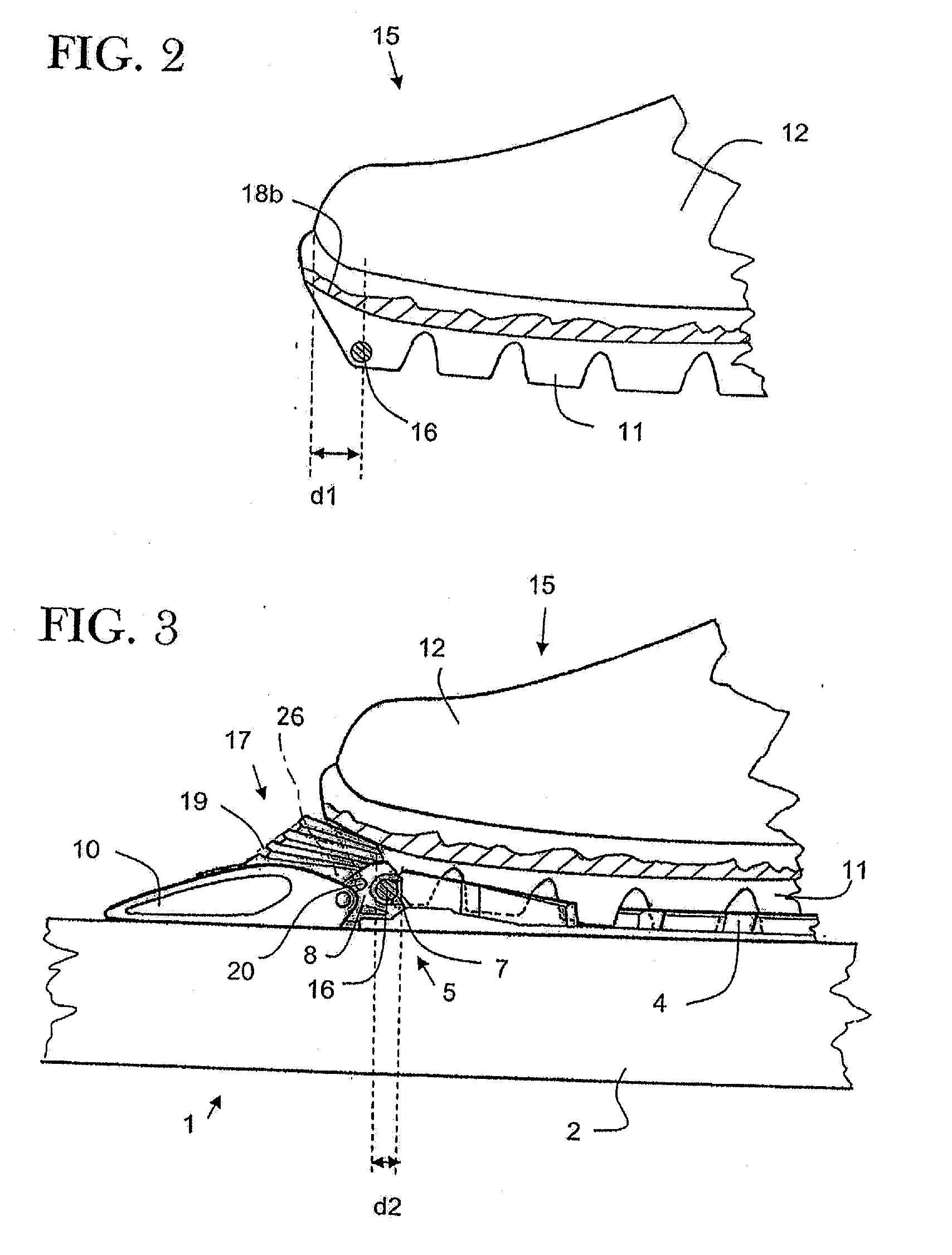
[0036]FIGS. 1 to 6 show a ski and a boot for the practice of Nordic skiing, in which the skier alternately raises and lowers the heel, such as when practicing Telemark skiing, ski touring, roller skiing, or cross-country skiing. In the following description, the various types of skiing encompassed within the disciplines known generally as Nordic skiing will be referred to generally as cross-country skiing, or even simply as skiing, although such reference should not be interpreted in a way that has a limiting effect on the scope of the invention.
[0037]The ski 1 comprises a gliding board 2 on which a binding 3 is mounted.
[0038]The binding 3 includes a plate 4, or base, adapted to be fixed to the gliding board 2, as well as a retaining device 5 fo...
PUM
 Abstract
Description
Claims
Application Information