
Dual column gang outlets for minimizing installation space

a technology of installation space and double column, applied in the direction of emergency power supply arrangement, coupling device connection, manufacturing tools, etc., can solve the problems of limiting the number of outlets and excluding the use of industry standards, so as to facilitate the inclusion of a large number of power outlets, facilitate the securing of power cords, and prevent accidental decoupling of power cords.

Active Publication Date: 2010-12-16
AMERICA POWER CONVERSION CORP
View PDF76 Cites 31 Cited by
  • Summary
  • Abstract
  • Description
  • Claims
  • Application Information

AI Technical Summary

Benefits of technology

The present patent relates to power outlet units that include ganged electrical outlets for use in equipment such as power distribution units or uninterruptible power supplies. The power outlet units have a locking feature that prevents accidental decoupling of power cords from the outlets. The power outlet units have a high number of power outlets in a given area and are designed to securely hold power cords. The power outlet units also include a power input terminal and a housing with at least one slot or recess to retain the locking tab of a locking power cord. The power outlet units are designed to provide power to the equipment in a safe and secure manner.

Problems solved by technology

This gap between outlets limits the number of outlets that can be included within a given area and precludes the use of industry standard ganged receptacles if the locking feature is desired.

Method used


Image

  • Dual column gang outlets for minimizing installation space
  • Dual column gang outlets for minimizing installation space
  • Dual column gang outlets for minimizing installation space

Examples


Embodiment Construction

[0038]This invention is not limited in its application to the details of construction and the arrangement of components set forth in the following description or illustrated in the drawings. The invention is capable of other embodiments and of being practiced or of being carried out in various ways. Also, the phraseology and terminology used herein is for the purpose of description and should not be regarded as limiting. The use of “including,”“comprising,” or “having,”“containing,”“involving,” and variations thereof herein, is meant to encompass the items listed thereafter and equivalents thereof as well as additional items.

[0039]The present disclosure is directed toward locking electrical outlet units and to power distribution unit (PDU) or uninterruptible power supply (UPS) products which include locking electrical outlets, for example, electrical outlets conforming to the International Electrotechnical Commission (IEC) IEC-C13 or IEC-C19 standards. These outlets may be used in c...


PUM

PropertyMeasurementUnit
surface areaaaaaaaaaaa
widthaaaaaaaaaa

Abstract

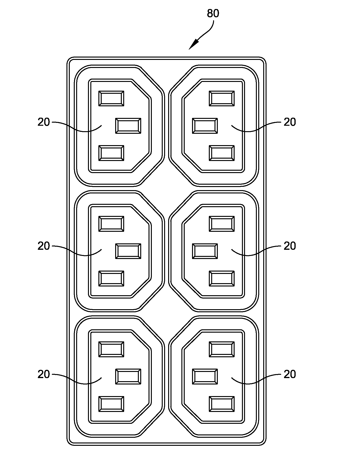
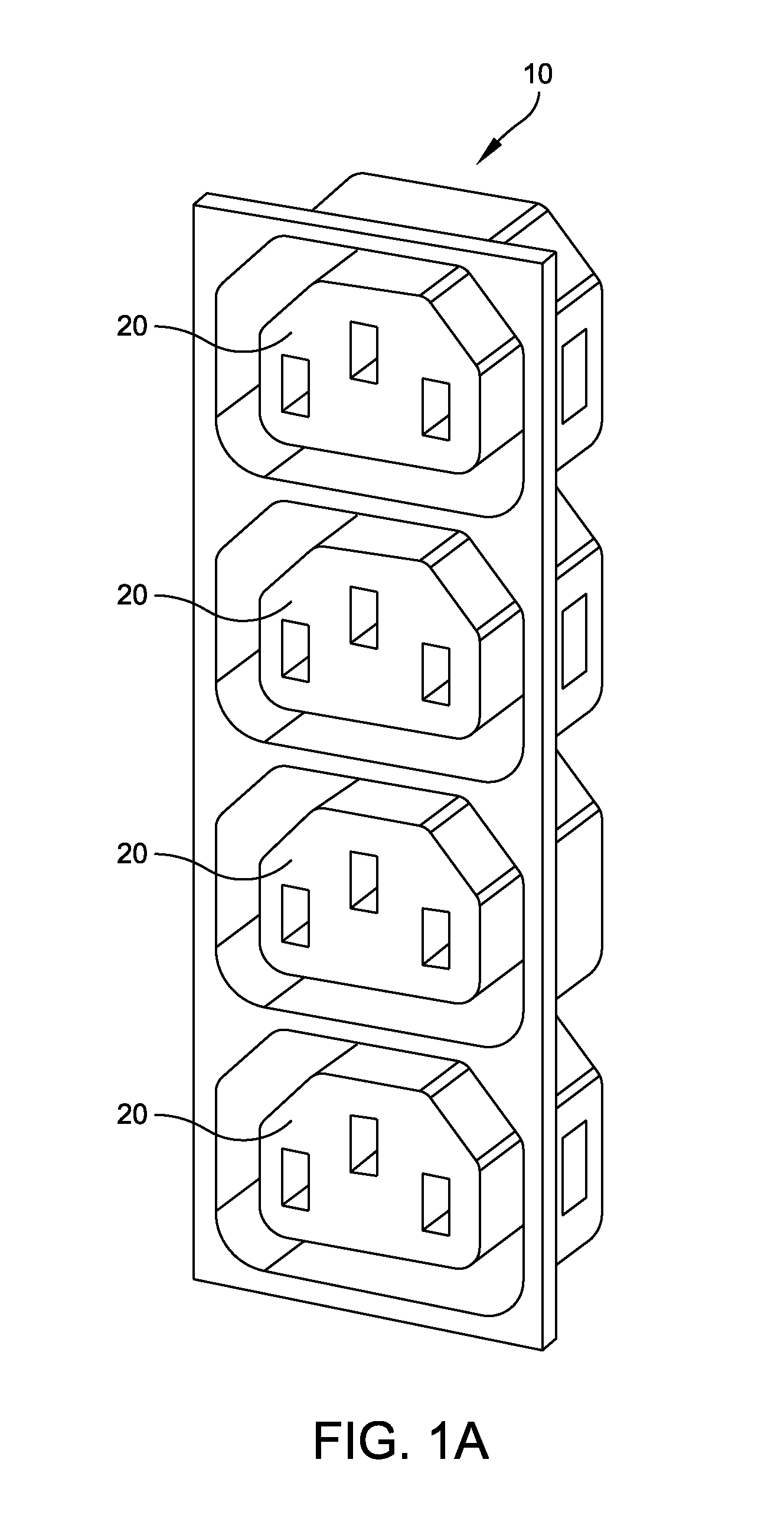
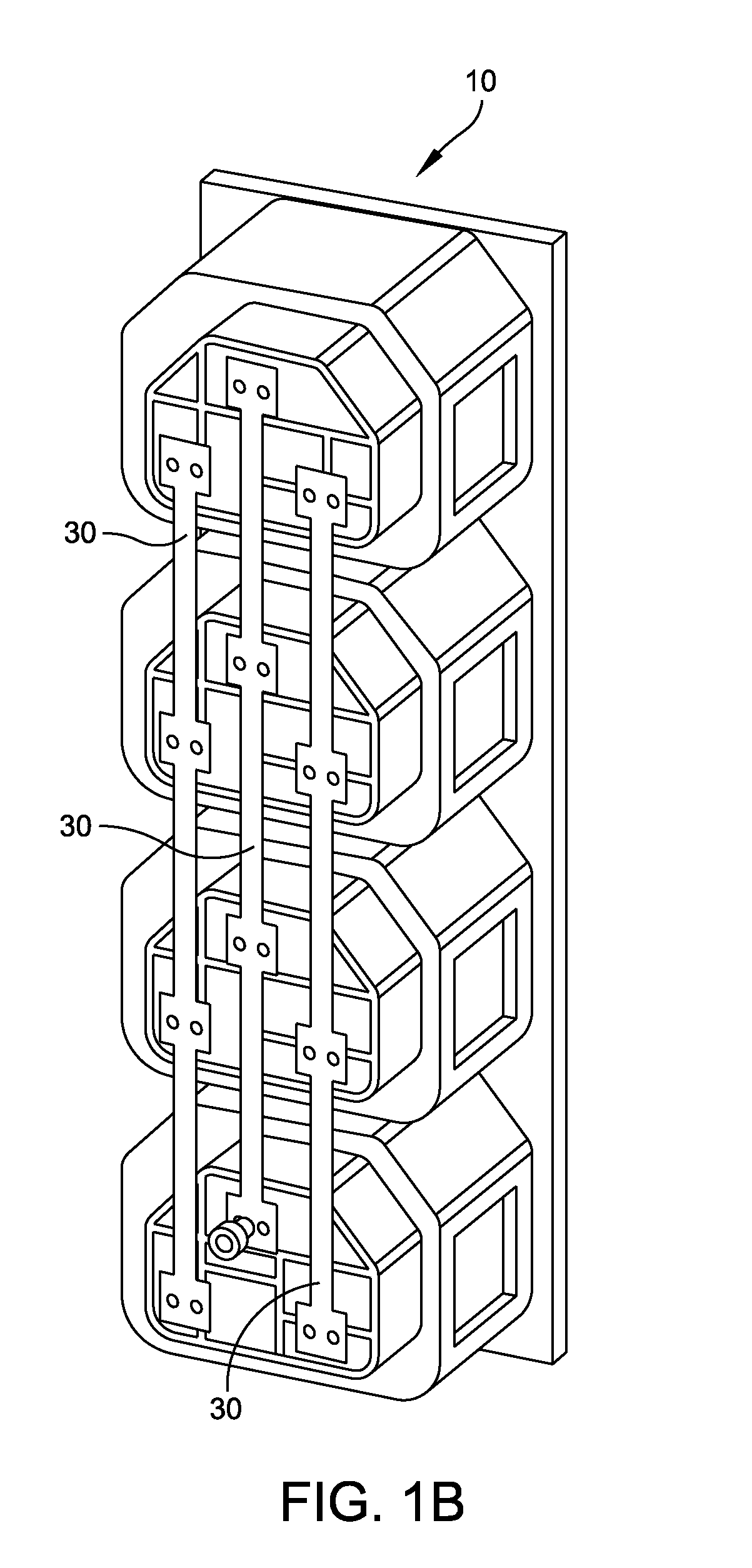
A power distribution unit disclosed herein includes a plurality of power outlets arranged in adjacent columns, the first and the second terminals of the power outlets in a first column formed along a first line, the first and the second terminals of the power outlets in a second column formed along a second line, ground terminals of the power outlets in the first column formed along a third line, and ground terminals of the power outlets of the second column formed along a fourth line, wherein the first line, the second line, the third line, and the fourth line are arranged in parallel, and wherein the plurality of power outlets are arranged in one of an arrangement in which the third and fourth lines are positioned between the first and second lines, and an arrangement in which the first and second lines are positioned between the third and fourth lines.

Description

RELATED APPLICATIONS[0001]This application claims priority under 35 U.S.C. § 119(e) to U.S. Provisional Application Ser. No. 61 / 186,241, entitled “DUAL ROW IEC C13 AND / OR C19 GANG OUTLETS FOR MINIMIZING INSTALLATION SPACE,” filed on Jun. 11, 2009, which is herein incorporated by reference in its entirety.BACKGROUND OF INVENTION[0002]1. Field of Invention[0003]The present disclosure is directed to locking electrical outlet units, and more specifically, to power distribution unit (PDU) products which include locking electrical outlets, for example, electrical outlets conforming to the International Electrotechnical Commission (IEC) IEC 60320 standard, including IEC-C13 or IEC-C19 compliant electrical outlets.[0004]2. Discussion of Related Art[0005]The arrangement of outlets in many conventional locking outlet technologies includes a gap between individual (non-ganged) outlets to accommodate the locking feature. This gap between outlets limits the number of outlets that can be included...

Claims


Application Information

Patent Timeline
Patent Type & Authority Applications(United States)
IPC IPC(8): H02J7/34H01R13/10H01R13/15B23P11/00
CPCH01R13/6272H01R25/006Y10T307/527Y10T307/344Y10T29/49826
Inventor JANSMA, MICHAELJIANG, YUCHUNDONJON, JIM PHILLIP
Owner AMERICA POWER CONVERSION CORP
Learn More