Aerosol-generating system comprising moveable cartridge

An aerosol generation and air flow technology, which can be used in drug devices, therapeutic nebulizers, inhalers, etc., and can solve problems such as liquid residues

Active Publication Date: 2017-08-01
PHILIP MORRIS PROD SA
View PDF6 Cites 5 Cited by
  • Summary
  • Abstract
  • Description
  • Claims
  • Application Information

AI Technical Summary

Problems solved by technology

However, this has the additional disadvantage that after the cartridge is consumed t

Method used


Image

  • Aerosol-generating system comprising moveable cartridge
  • Aerosol-generating system comprising moveable cartridge
  • Aerosol-generating system comprising moveable cartridge

Examples


Embodiment Construction

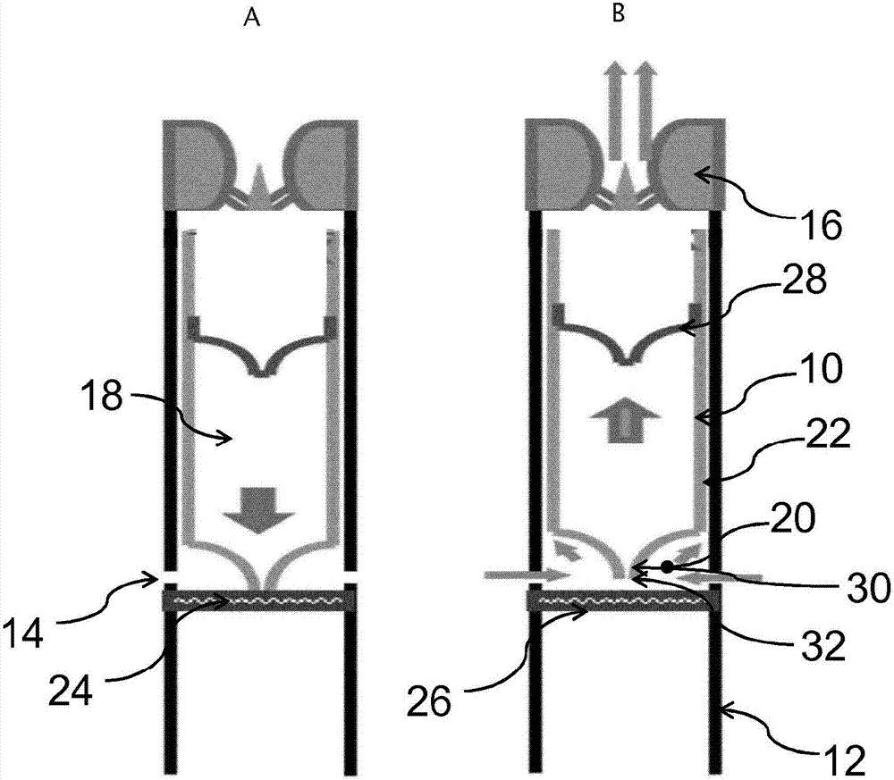
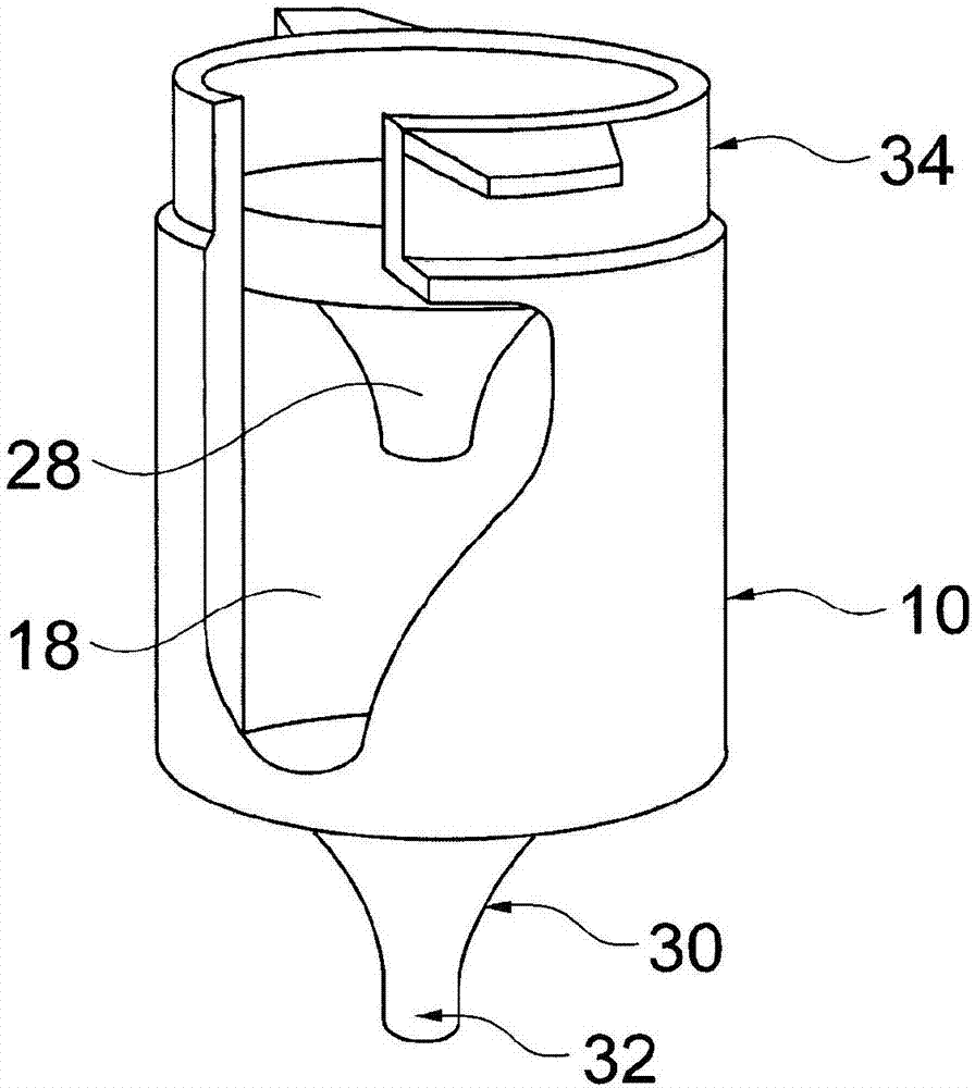
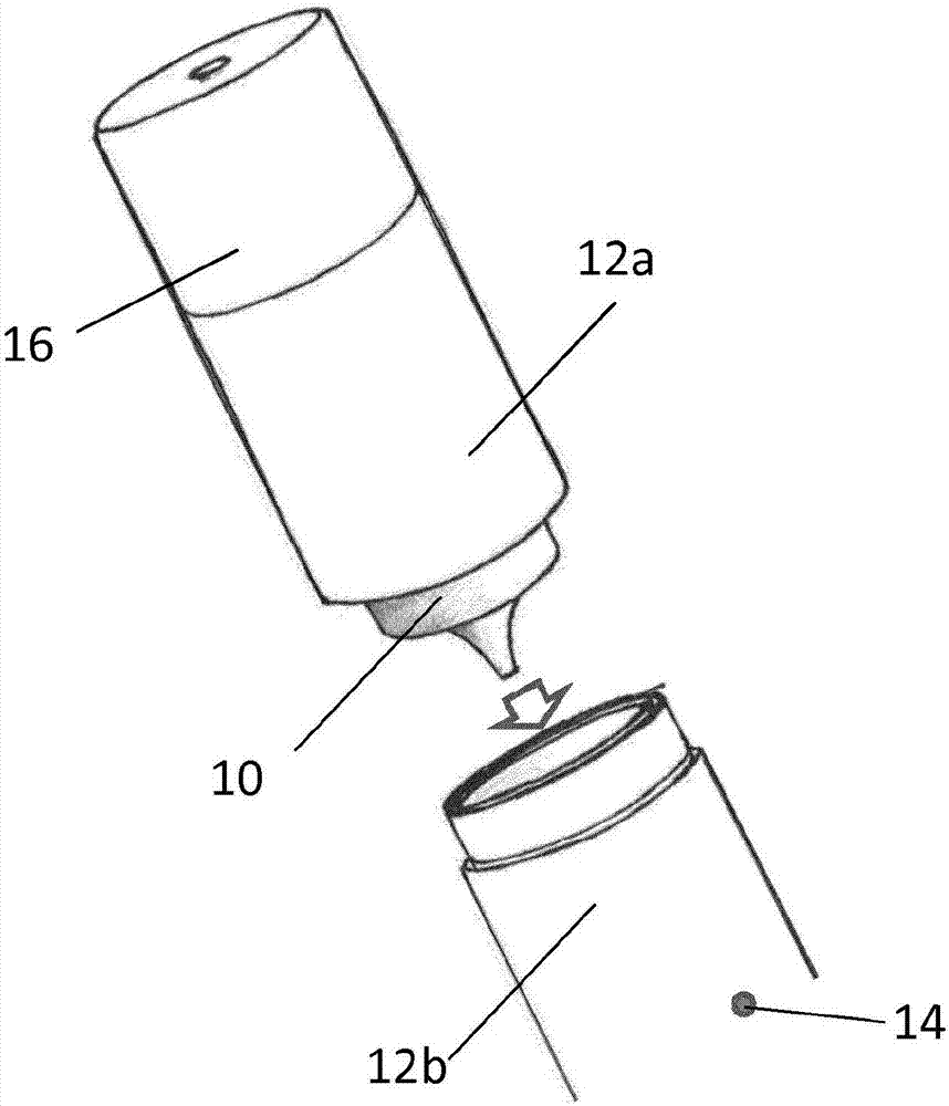
[0057] figure 1 a and figure 1 b shows a schematic diagram of an aerosol generating system incorporating a movable cartridge 10 containing an aerosol generating liquid. exist figure 1 a and figure 1 In b, the aerosol generating system is an electronic cigarette comprising a housing 12 with an air inlet 14 and a mouthpiece 16 representing the air outlet. An airflow path 18 is defined between the air inlet 14 and the mouthpiece 16 . The airflow path directs airflow from the air inlet 14 , through the aerosol-forming chamber 20 , through the circular gap 22 between the barrel 10 and the inner surface of the housing 12 to the mouthpiece 16 . A heater element 24 is disposed at a distal wall 26 of the aerosol-forming chamber. The cartridge 10 includes a movably mounted piston 28 and a nozzle 30 having a discharge end 32 for dispensing liquid from a liquid storage portion 18 inside the cartridge 10 onto the heater element 24 . The liquid storage portion 18 corresponds to the vo...


PUM


Abstract

An aerosol-generating system comprising moveable cartridge is disclosed. The aerosol-generating system comprises a housing (12), with an air inlet (14) and an air outlet (16) defining an air flow channel (18), a heater element (24) and a cartridge (10) moveably mounted in the housing (12) and reversibly displaceable from a first position into a second position. The cartridge (10) comprises a liquid storage portion (18) for holding an aerosol-generating liquid and has an opening for delivery of the aerosol-generating liquid, the cartridge further comprises a moveable plunger (28). When an airstream is created between the air inlet (14) and the air outlet (16), the cartridge (10) is moved by the airstream within the housing (12) and the movement of the cartridge (10) activates the release of a portion of the aerosol-generating liquid through the opening of the cartridge (10).

Description

technical field [0001] The present invention relates to an aerosol generating system comprising a cartridge for containing a liquid and a heater assembly suitable for evaporating the liquid. In particular, the present invention relates to hand-held aerosol-generating systems, such as electrically operated aerosol-generating systems. Background technique [0002] Electrically operated aerosol-generating systems that vaporize a liquid by heating to form an aerosol typically include a coil of wire wrapped around a capillary material containing the liquid. Current passing through the wire causes resistive heating of the wire, which evaporates the liquid in the capillary material. The capillary material is generally held within the airflow path, allowing air to be drawn through the wick and entrain the vapor. The vapor is then cooled to form an aerosol. [0003] In addition to delivering liquid from the liquid reservoir to the heater assembly, the wick also represents the clos...

Claims


Application Information

Patent Timeline
IPC IPC(8): A24F47/00A61M15/00A24F40/10A24F40/42A24F40/48
CPCA61M15/0091A61M15/06A61M2205/0211A61M11/042A61M15/0061A61M15/0093A61M16/207A61M2209/045A24F40/10A24F40/48A24F40/42A24F40/485A24B15/167A24F47/00
Inventor R·N·巴蒂斯塔
Owner PHILIP MORRIS PROD SA
Why Eureka
Try Eureka