Electrical connector

US20070037430A1Active Publication Date: 2007-02-15ITT MFG ENTERPRISES INC
5 Cites 9 Cited by

Patent Information

Authority / Receiving Office
US · United States
Current Assignee / Owner
Publication Date
2007-02-15

Smart Images

  • Figure 1
    Figure 1
  • Figure 2
    Figure 2
  • Figure 3
    Figure 3
Patent Text Reader

Abstract

A bayonet electrical connector has a spring loaded safety pin for locking the bayonet coupling. The pin projects into a recess, and a sleeve surrounds the part having the recess. The sleeve has a tab which projects into the recess, the sleeve being slidable to make the tab depress the pin against the spring bias of the pin, thereby to enable subsequent disconnection of the bayonet coupling. This design maintains a locking mechanism to prevent accidental decoupling of the bayonet connection, but makes the decoupling process simpler, by using, sliding of the sleeve and twisting to release the bayonet coupling.
Need to check novelty before this filing date? Find Prior Art

Description

CROSS-REFERENCE

[0001] This is a Continuation-In-Part of PCT / GB2005 / 000291 filed 27 Jan. 2005 which designated the US and which claimed priority from British patent application GB 0404280.0 filed 26 Feb. 2004.BACKGROUND OF THE INVENTION

[0002] This invention relates to electrical connectors, and more particularly to high power safety connectors.

[0003] The terminals of high current electrical connectors are typically much larger than for domestic electrical connectors, and it can be possible for a person to insert a finger or other object into a socket opening and touch electrically live components within the socket.

[0004] There are various designs of electrical connector which provide a safety feature, to reduce the risk of live contacts being accessible when the connector is disconnected.

[0005] U.S. Pat. No. 6,309,231 discloses an electrical connector in which the mating surfaces of the male and female connectors present only insulating components to the user. Furthermore, to se...

Examples

Embodiment Construction

[0030] Before describing the improved connector of the invention, the operation of the connector of U.S. Pat. No. 6,309,231 will first be described.

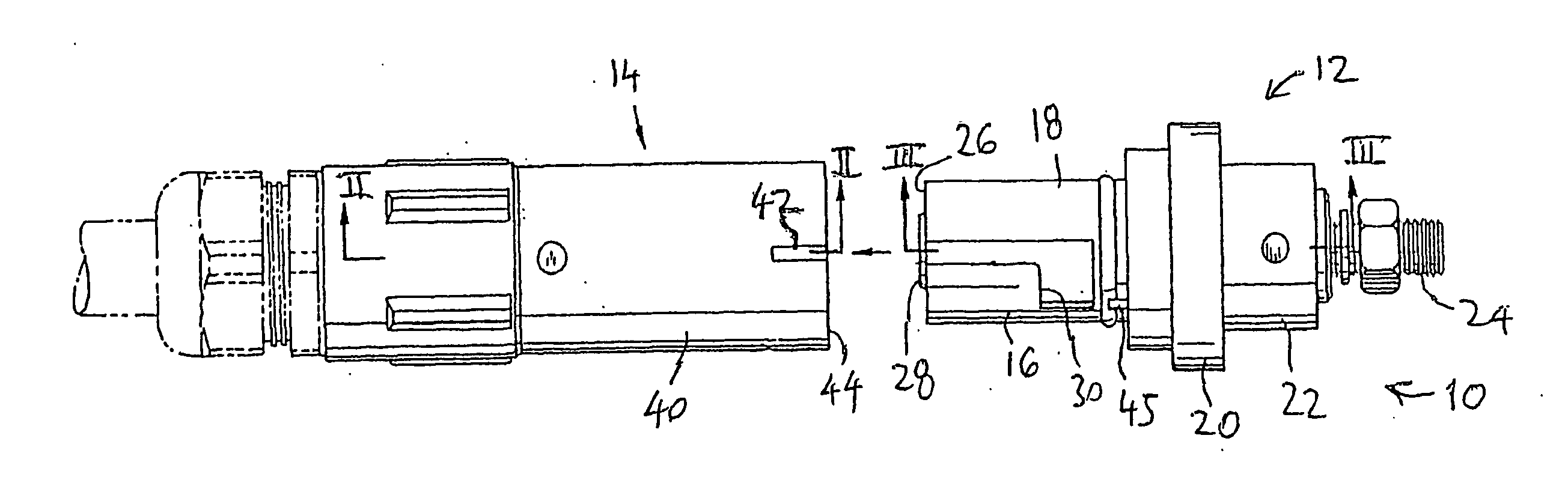
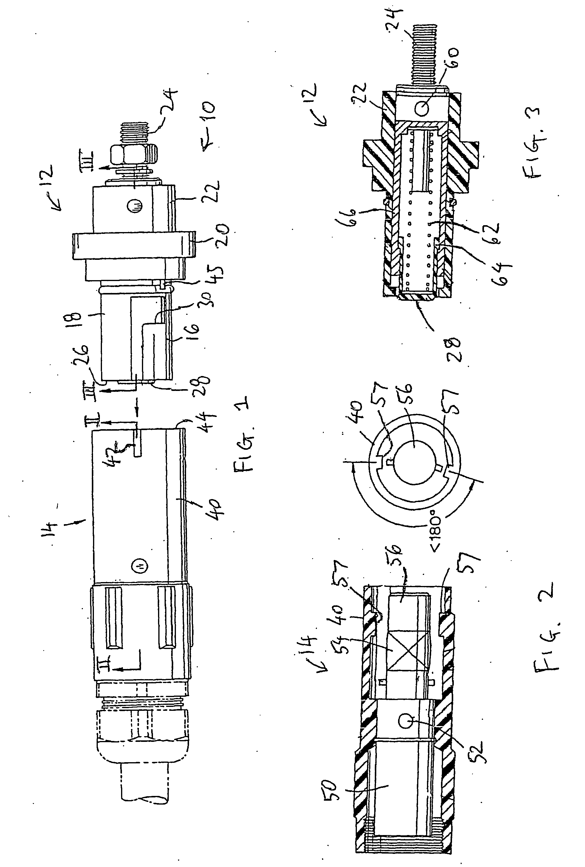
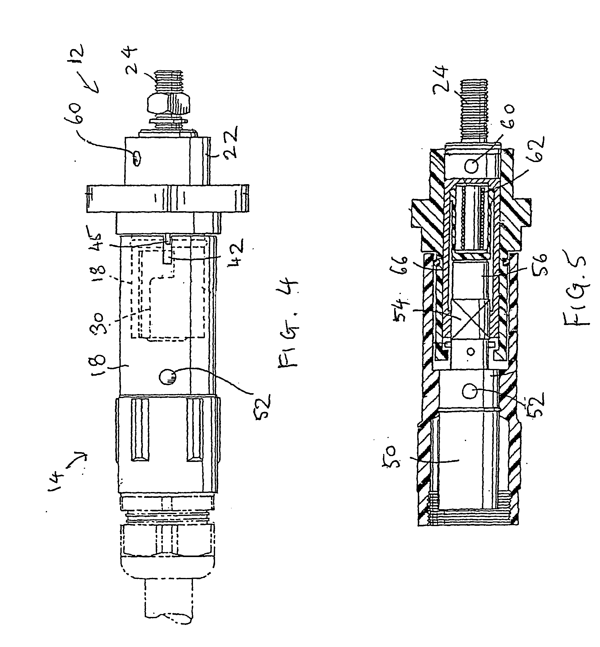
[0031]FIG. 1 shows the power connector assembly of U.S. Pat. No. 6,309,231, generally indicated at 10 in an uncoupled position.

[0032] The assembly 10 has a male connector 12 and a female connector 14. The male connector 12 has a body 16 formed from an electrically insulating material, such as plastic. The male connector 12 has a cylindrical male portion 18, a flange 20 and a rear part 22. The male connector is for connection to a source of high voltage using a conventional threaded connector 24.

[0033] The male connector has an end face 26, and an insulating pin 28 projects slightly beyond the end face 26. The male portion 18 has two slots 30, which are used to define a bayonet type coupling with the female connector 14.

[0034] The female connector 14 has a cylindrical electrically non-conductive body 40 having a slot 42 extending inwa...