Table apparatus for a vehicle seat

a vehicle seat and table technology, applied in the field of seat seat stowage apparatus, can solve the problems of reducing the intuitiveness of such assemblies and storage problems, and achieve the effects of reducing the number of components, facilitating passenger egress and access, and simplifying intuitive kinematics

Active Publication Date: 2010-12-23
THOMPSON AERO SEATING
View PDF15 Cites 41 Cited by
  • Summary
  • Abstract
  • Description
  • Claims
  • Application Information

AI Technical Summary

Benefits of technology

[0019]Accordingly, the invention provides an in-seat table apparatus comprising one or more table leafs that can be are stored in a horizontally related plane and may be secured in the stowed configuration using a suitable latch mechanism. The table can be moved to a fully deployed position by either pulling to the side or to the front of its stored location. Smooth operation is achieved by a using mechanism or plurality of mechanisms, such as two parallel links, gears or a chain / belt driven mechanism, that ensures the table travels upon a predetermined parallel path during deployment / stowing. The relationship between pivot positions and mechanism may be optimised depending on the users requirements primarily to ensure optimum table coverage over a specified distance. This design allows for simpler intuitive kinematics and in some cases a reduction in the number of components required. Over the specified usable distance, the table may be maintained parallel to the user. However, when the table is at least partially deployed, passenger egress and access can be improved by enabling the table to be pivoted independently, away from the seated position.
[0020]In one embodiment, the apparatus includes an actuation means which raises the intuitiveness by ‘presenting the table’ to the passenger. This initial presentation may perhaps be to a predetermined distance and occur at a controlled speed if required.

Problems solved by technology

However, the multiplicity of translational and rotational movements required for table deployment and stowage tend to overcomplicate and reduce the intuitiveness of such assemblies.
Another problem with such designs is that the contained rigid mechanisms cause the table to interfere with passenger access and egress whilst the table is in the deployed state and the upright storage position can cause storage problems where space within the console is limited, or example due to installations within the console, or the need for access beneath the console, for example for the legs of a passenger in a seat behind.

Method used


Image

  • Table apparatus for a vehicle seat
  • Table apparatus for a vehicle seat
  • Table apparatus for a vehicle seat

Examples


Embodiment Construction

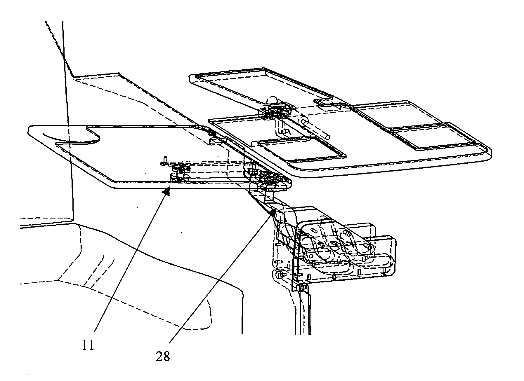
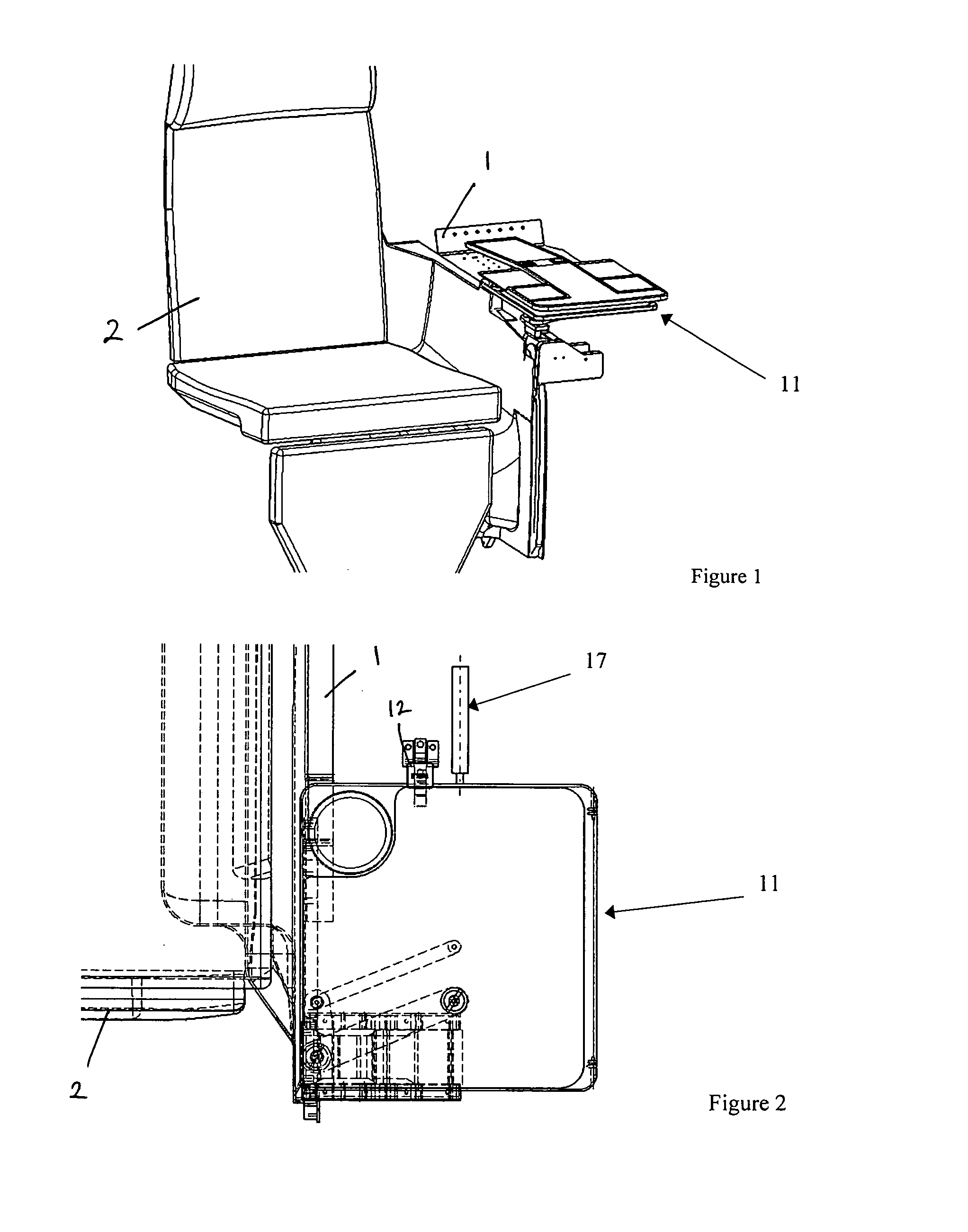
[0039]FIG. 1 shows a perspective view of a table 11 embodied within a suitable cosmetic shroud, typically comprising a console 1 located alongside a seat 2, typically a business class airline seat. Supporting structures have been removed for clarity of view. In the position shown in FIG. 1, the table 11 is stowed horizontally, parallel to and beneath a horizontal upper surface of the console 1 within an upper region of the console 1.

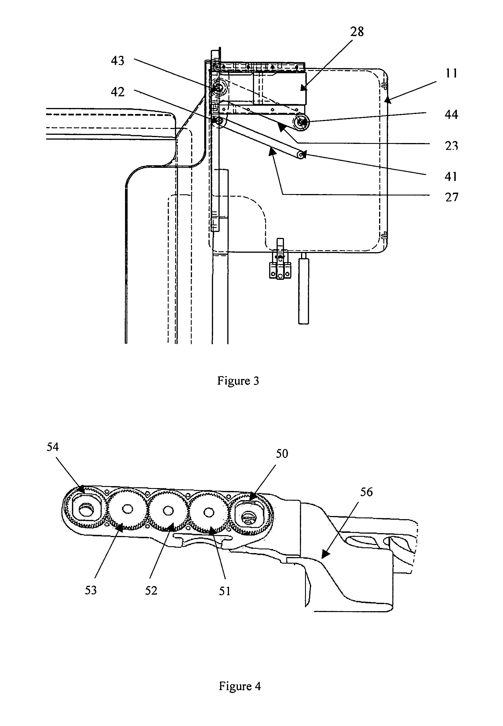
[0040]As illustrated in FIG. 2, whilst in the stowed position, the table 11 can be secured, if required, by a suitable latch mechanism 12. The table 11 is connected to the console / seat assembly by linkage means providing guided movement of the table 11 between stowed and operative positions, as will be described below. In the stowed position the deployment actuation means17, comprising a biasing means biasing the table towards an extended or operative deployed position, is compressed between its fixed mount and the rear table face, the table 11 being mai...


PUM


Abstract

A table apparatus for a vehicle seat comprising a table, having at least one table leaf, and a table support mechanism, wherein the table support mechanism enables translational movement of the table between a substantially horizontal stowed configuration and a deployed configuration. In a preferred embodiment, the linkage arrangement of the table support mechanism comprises at least one substantially horizontally extending support arm extending from a table support member, the table being mounted upon a distal end of the support arm, the support arm being pivotally connected to the table support member for rotation about a first pivot axis in a substantially horizontal plane about the support member, the table being pivotally connected to said distal end of the support arm for rotation about a second pivot axis in a substantially horizontal plane, linkage means being provided for normally constraining rotational movement of the table about the second pivot axis to follow rotational movement of the support arm about the first pivot axis such that the rearmost table face remains substantially aligned to the user such that the table orientation is maintained substantially parallel to its final deployed position during movement between said stowed and deployed configurations

Description

[0001]This application is a 35 USC 371 National Phase filing of PCT / EP2008 / 004116 filed May 24, 2007, which claims the benefit of United Kingdom patent application 0709973.2, filed May 24, 2007, the disclosures of which are incorporated herein by reference in their entireties.FIELD OF THE INVENTION[0002]The present invention relates to a stowable table apparatus for a seat, and in particular to an in-seat table apparatus for vehicles and most particularly for aircraft.BACKGROUND TO INVENTION[0003]Conventional in-seat tables consist of bi-fold or single leaf tables, which are stored in an upright position, typically within a console or armrest to one side of the seat, and, in use, are translated and or rotated onto the required plane. Positioning relative to the passenger is achieved through the use of parallel slides and hinges.[0004]However, the multiplicity of translational and rotational movements required for table deployment and stowage tend to overcomplicate and reduce the int...

Claims


Application Information

Patent Timeline
Patent Type & Authority Applications(United States)
IPC IPC(8): A47B37/00A47B13/00
CPCB64D11/06B64D11/0646B64D11/0638B60N3/001
Inventor HANNA, JASON KYLEGORDON, PHILIPTHOMPSON, JAMES
Owner THOMPSON AERO SEATING
Why Eureka
Try Eureka