
Intake limiting device for document shredder

Inactive Publication Date: 2010-12-23
MARTIN YALE INDS
View PDF7 Cites 0 Cited by
  • Summary
  • Abstract
  • Description
  • Claims
  • Application Information

AI Technical Summary

Benefits of technology

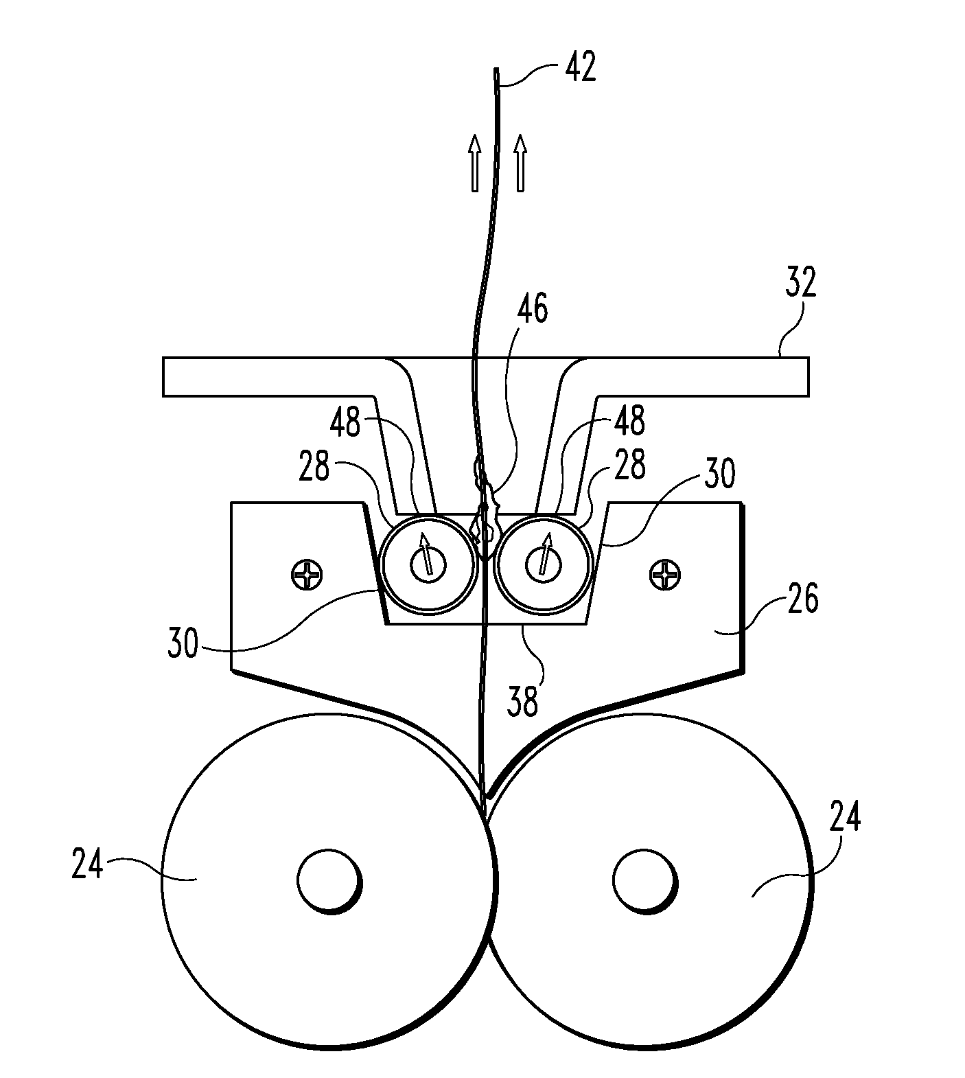
[0004]A shredder intake limiting device is disclosed, comprising two intake bars disposed in a generally parallel configuration and defining an intake opening between the intake bars for directing sheet material into a shredder. The intake bars are supported by supports which have a lower floor surface and upwardly-diverging sidewall surfaces. The initial horizontal separation of the intake bars is limited to a first maximum distance defined by the separation distance of the sidewall surfaces when the sheet material is being inserted downward into the shredder. The angle of the sidewall surfaces allows the intake bars to travel upward and the horizontal separation distance of the intake bars to increase beyond the first maximum distance when sheet material is being removed from the shredder in an upward direction.
[0005]According to another aspect of the disclosure, a shredder intake limiting device is disclosed, comprising two intake bars disposed in a generally parallel configuration and defining an intake opening between the intake bars for directing sheet material into the shredder. The intake bars are supported in slots defined in the supports, the slots being angled in an upwardly-diverging fashion, with each one of the slots having an upper and lower end. The initial horizontal separation of the intake bars is limited to a first maximum distance when the intake bars are resting in the lower ends of the slots and the sheet material is being inserted downward into the shredder. The angle of the slots allows the intake bars to travel upward and the horizontal separation distance of the intake bars to increase beyond the first maximum distance when sheet material is being removed from the shredder in an upward direction.
[0006]According to another aspect of the disclosure, a device is disclosed, comprising a housing, two rotatable interlocking cutting heads mounted within the housing for shredding sheet material, and two intake bars disposed in a generally parallel configuration above the cutting heads and defining an intake opening between the intake bars for directing sheet material into the cutting heads. The intake bars are supported by supports which have a lower floor surface and upwardly-diverging sidewall surfaces. The horizontal separation distance of the intake bars is limited to a first maximum distance by the angled sidewall surfaces when the sheet material is being inserted downward into the shredder. The angle of the sidewall surfaces allows the intake bars to travel upward and the horizontal separation distance of the intake bars to increase beyond the first maximum distance when sheet material is being removed from the device in an upward direction.

Problems solved by technology

If material having an excessive thickness reaches the cutting heads, jamming and / or damage may occur.
A problem occurs, however, when an acceptable amount of material is fed through the intake rollers, but wrinkles or otherwise bunches up during the feeding process.
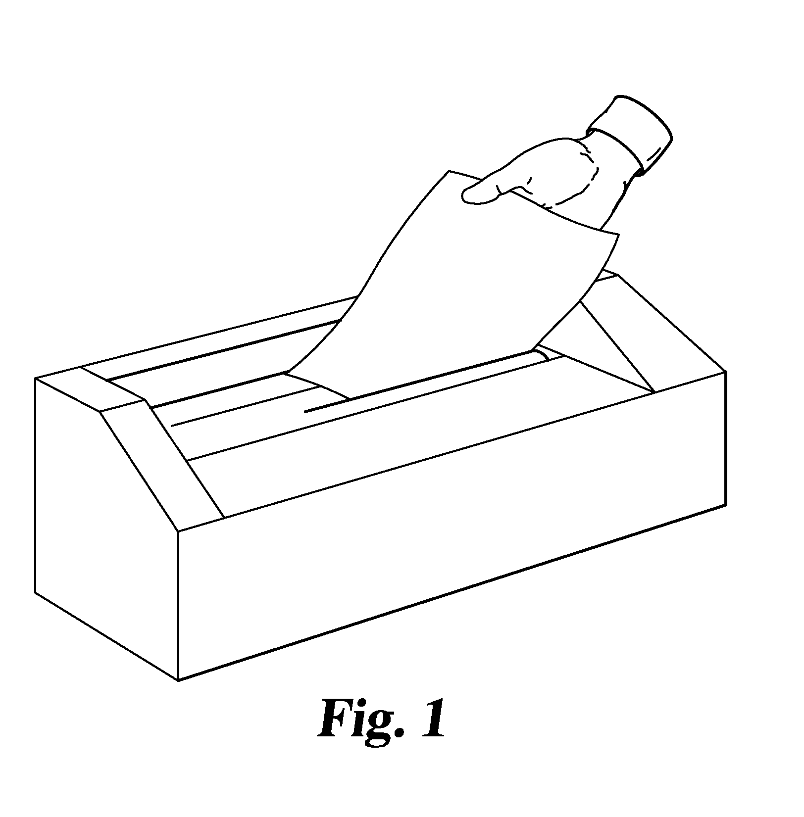
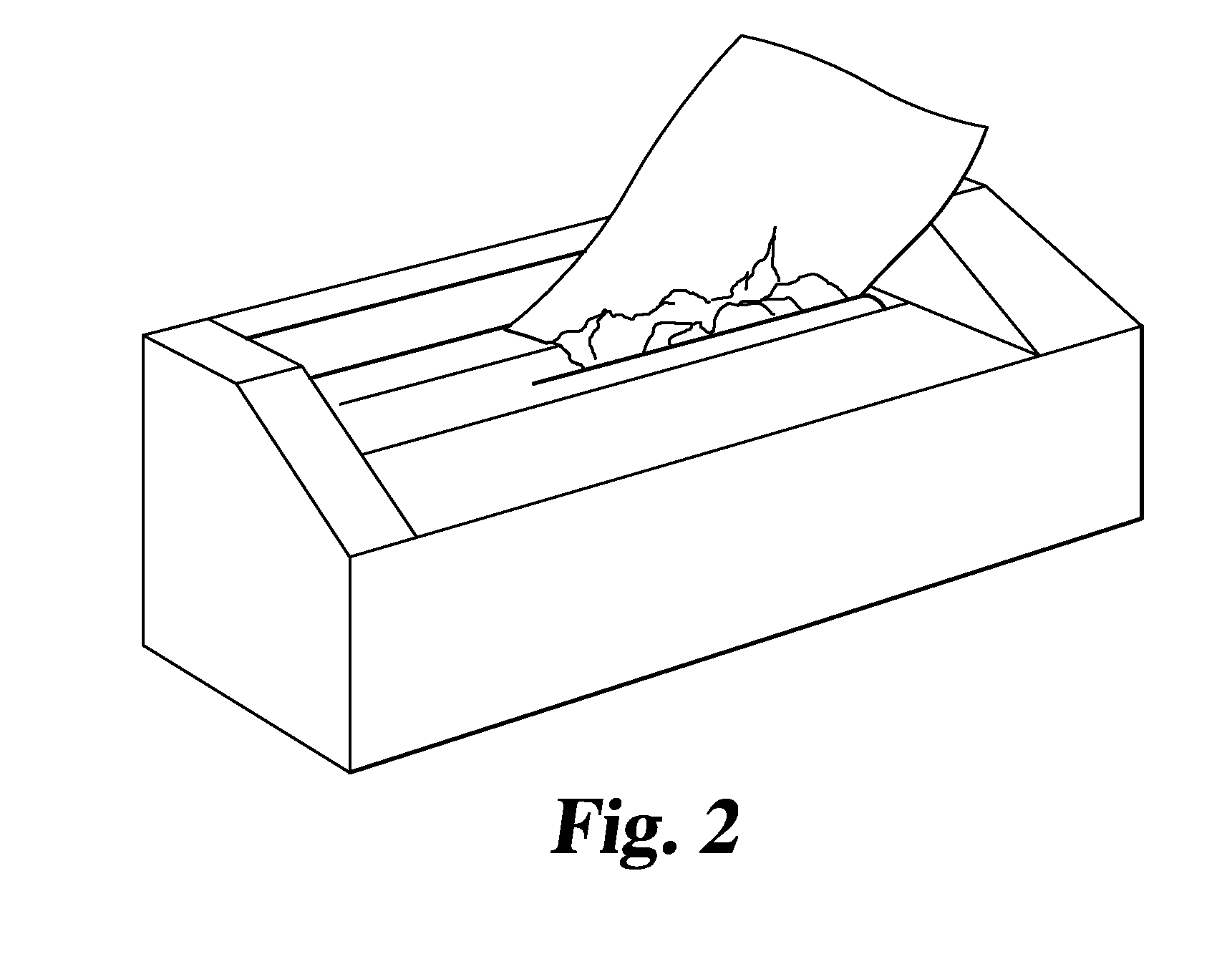
For example, if paper is inserted in a crooked fashion, such that the side edges of the paper make contact with the side edges of the intake slot after some portion of the paper has already been engaged by the cutting heads (see FIG. 1), the paper will fold over on itself near the side edges as it is pulled through (see FIG. 2), causing a jam in the intake rollers.
However, it is often difficult for the user to remove the paper once a jam has occurred, especially if the folded portion or “blister” has managed to get past the intake rollers before the shredder has stopped.
When the user tugs on the jammed paper in an attempt to remove it, it may tear, leaving only a small, unreachable portion of paper left within the intake rollers.
This not only causes frustration, but also presents a safety hazard if the user is tempted to place his hands into the shredding machine in an attempt to retrieve the torn material.

Method used


Image

  • Intake limiting device for document shredder
  • Intake limiting device for document shredder
  • Intake limiting device for document shredder

Examples


Embodiment Construction

[0021]For the purposes of promoting an understanding of the principles of the invention, reference will now be made to the embodiment illustrated in the drawings and specific language will be used to describe the same. It will nevertheless be understood that no limitation of the scope of the invention is thereby intended. Alterations and modifications in the illustrated device, and further applications of the principles of the invention as illustrated therein are herein contemplated as would normally occur to one skilled in the art to which the invention relates.

[0022]Referring to FIG. 3, a perspective view of a shredder 20 according to one embodiment of the present disclosure is shown. Shredder 20 includes a housing 22 within which cutting heads 24 are mounted. The cutting heads 24 may comprise rotating cylinders or plates having cutting teeth or any other cutting means known in the art. In order to limit the overall thickness of material that can be inserted into the cutting heads...


PUM


Abstract

A shredder intake limiting device having a pair of parallel bars, wherein the ends of the bars are supported by a pair of side supports. Each side support comprises a floor surface flanked by two upwardly-diverging sidewall surfaces. The angle of the sidewall surfaces is such that the bars will be prevented from separating beyond a desired limit when sheet material is being inserted downward into the shredder. When sheet material is being pulled upward during removal after a jam, the diverging angles of the sidewall surfaces will allow the bars to travel upward and the horizontal separation distance to increase, thereby allowing the jammed material to be easily removed.

Description

FIELD OF THE INVENTION[0001]The present invention relates in general to devices for shredding sheet-type material. More particularly, the present invention relates to an intake limiting device for a document shredder.BACKGROUND OF THE INVENTION[0002]Document shredding devices are known in the prior art and are available in a variety of sizes and designs. Most shredders utilize sharp cutting heads for shredding the inserted material, with the cutting heads typically optimized to handle a maximum material thickness (i.e., a maximum number of paper sheets). If material having an excessive thickness reaches the cutting heads, jamming and / or damage may occur. It is therefore important to limit the overall thickness of material that may be inserted into the shredder. This is typically accomplished by placing a pair of carefully spaced rollers in the intake path prior to the cutting heads. The spacing between the rollers is fixed to prevent excessively thick material from entering.[0003]A ...

Claims


Application Information

Patent Timeline
IPC IPC(8): B02C23/02
CPCB02C18/0007B02C23/02B02C18/2225B02C18/22
Inventor ODMAN, SHANON T.BOZARTH, BRADLEY L.
Owner MARTIN YALE INDS
Learn More