
RJ45 Connector

Active Publication Date: 2017-01-26
OPTICAL CABLE CORPORATION
View PDF0 Cites 0 Cited by
  • Summary
  • Abstract
  • Description
  • Claims
  • Application Information

AI Technical Summary

Benefits of technology

The invention provides a communication connector that improves signal transmission performance by improving the connection between a cable and a receptacle component. The connector includes a cable termination component with slots for wires, a receptacle component with insulation displacement contacts (IDCs) that align with the wires, a printed circuit board, and a lever arm for securely attaching the cable termination component to the receptacle component. The offset placement of the IDCs increases the separation distance between them, improving signal transmission between components. The invention also includes an electrical connectivity system with a plug and jack, and a lever arm for securely attaching the cable termination component to the receptacle component. The technical effects of the invention include improved signal transmission performance and reliability of the connection between cables and receptacles.

Problems solved by technology

Moreover, cable termination in a jack presently includes an arduous process requiring usage of tools such as punch down tools and pliers to electrically connect and hold together the insulation displacement contacts (IDCs) on the jack with the corresponding connector pairs of a cable.

Method used


Image

  • RJ45 Connector
  • RJ45 Connector
  • RJ45 Connector

Examples


Embodiment Construction

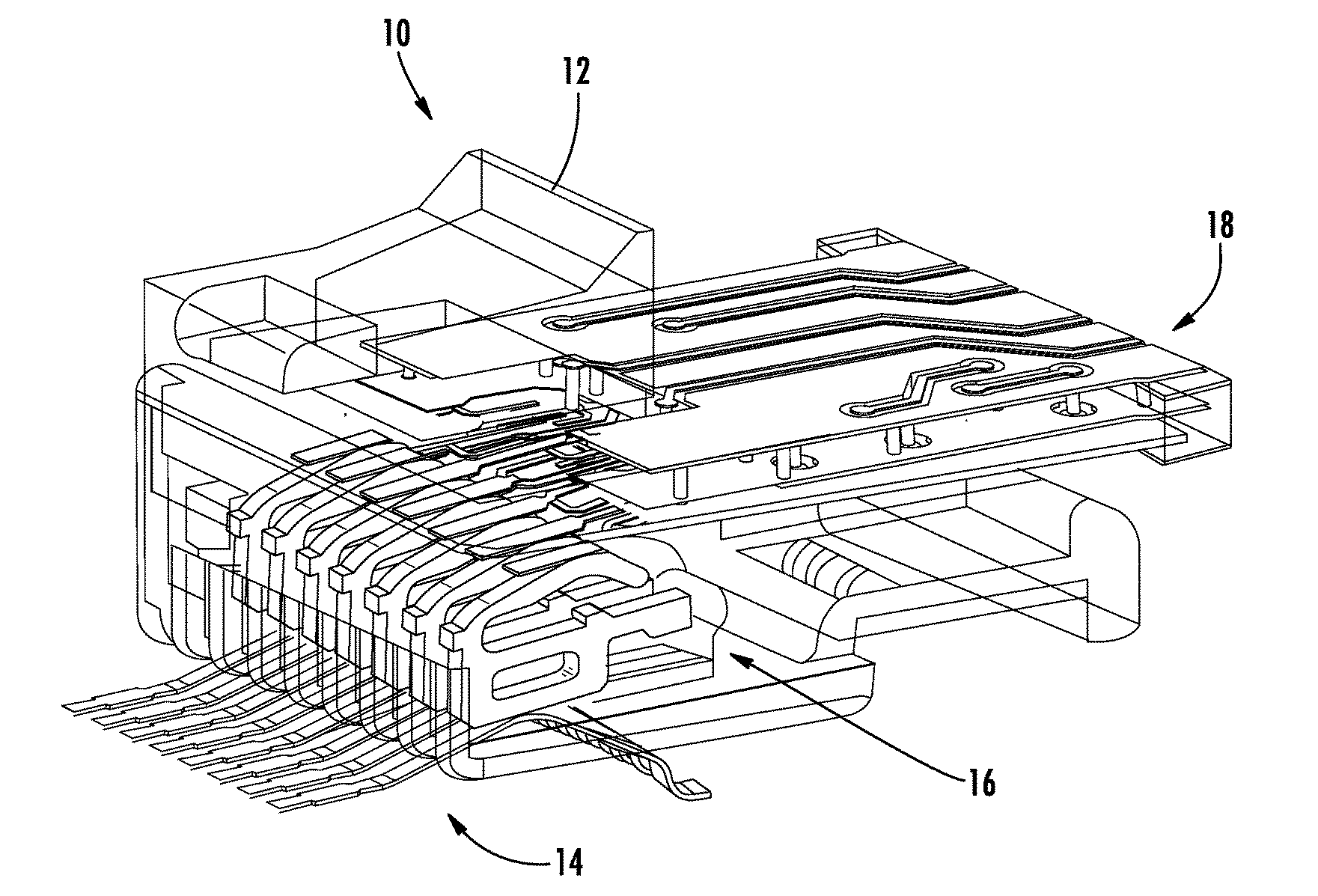
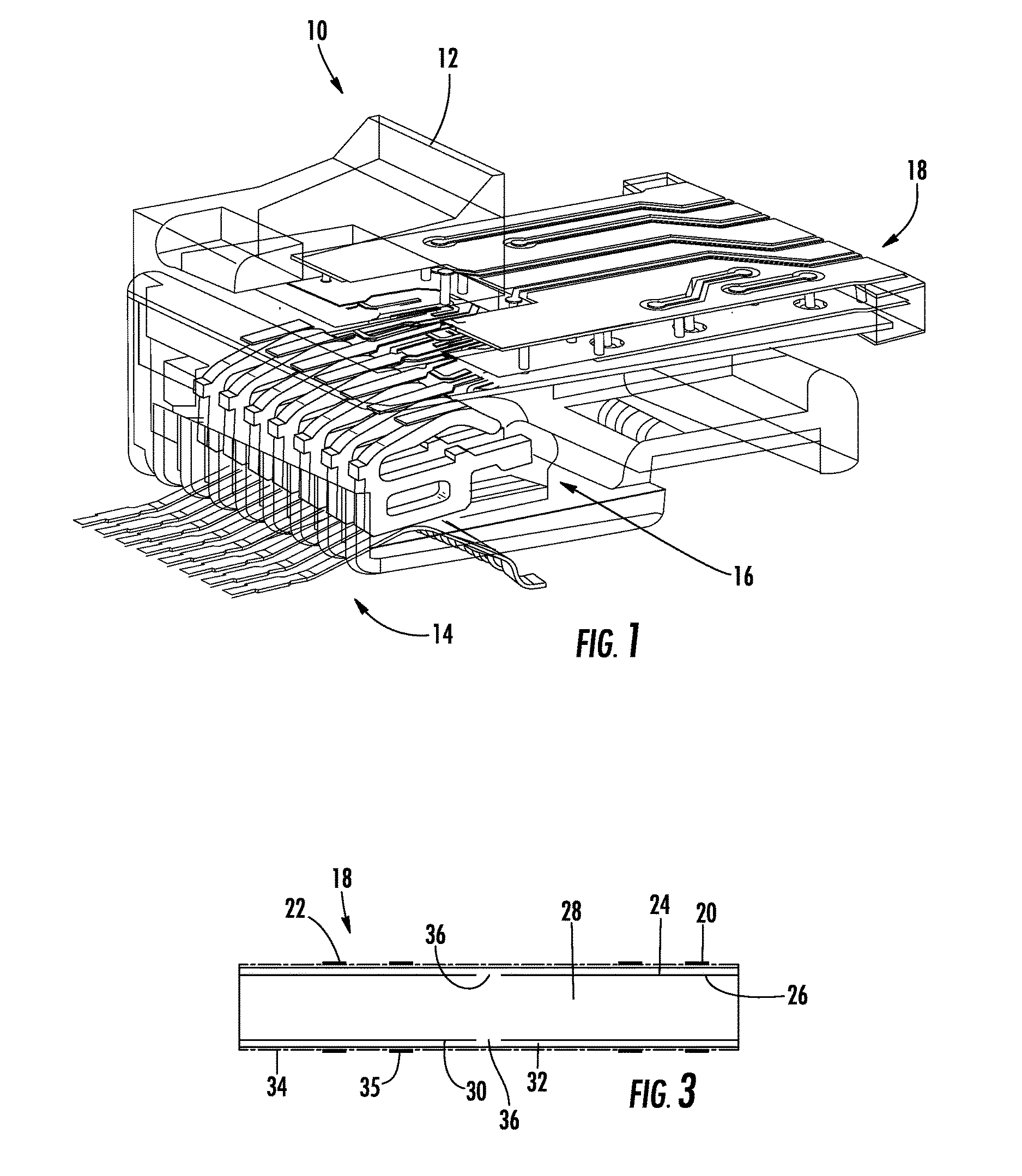
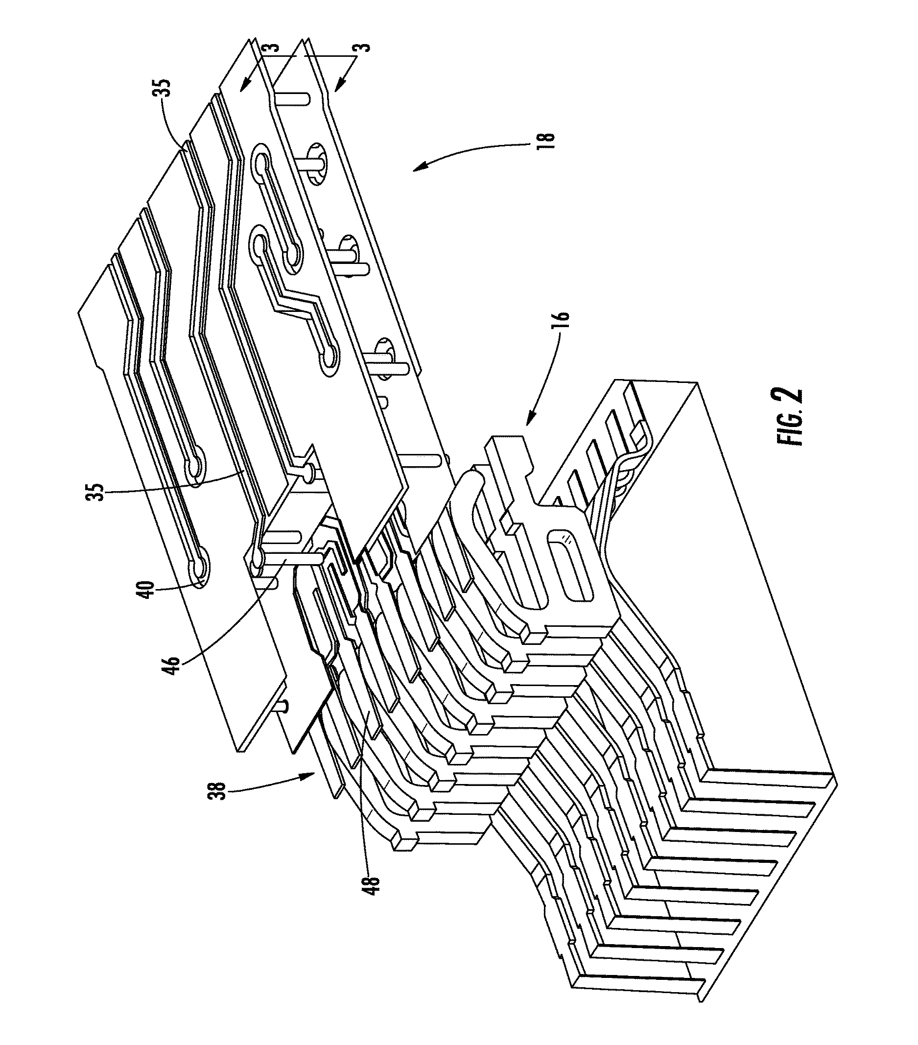
[0044]Referring now more particularly to FIG. 1, there is provided plug 10 having plastic body 12. Preferably, plug 10 has the connection architecture of a standard FCC RJ45 plug for connecting four signal pairs of conductors to a corresponding RJ45 jack, which except for jack contacts 14, is particularly illustrated in FIGS. 21-33. Plug 10 includes eight contacts 16 which are ordered in pairs in accordance with FCC standards. According to the FCC standards, pair 1 consists of the fourth and fifth contacts, pair 2 consists of the first and second contacts, pair 3 consists of the third and sixth contacts, and pair 4 consists of the seventh and eighth contacts.

[0045]Plug 10 also includes circuit board 18. Circuit board 18 preferably consists of seven layers of conductors and dielectric materials which is better illustrated in FIG. 3 which shows an inverted cross-section of circuit board 18. The top layer 20 of circuit board 18 includes circuit board traces corresponding to two of the ...


PUM


Abstract

There is provided a communication connector for improving signal transmission performance, the communication connector including a cable termination component being sized and configured for selective receipt of a plurality of conductor pairs of a cable; a plurality of slots on said cable termination component, wherein each wire of each of the plurality of conductor pairs may be selectively pressed into one of the plurality of slots; a receptacle component including a plurality of electrical contacts and a plurality of offset-positioned insulation displacement contacts (IDCs), each of the plurality of offset-positioned IDCs being aligned for engaged abutment with a corresponding one of the wires of the plurality of conductor pairs when the cable termination component and the receptacle component are coupled; a printed circuit board; and wherein the offset placement of the IDCs increases the separation distance between IDCs of another receptacle component when a plurality of the receptacle components are adjacent to one another, whereby a signal transmission is improved.

Description

RELATED APPLICATION[0001]This application is a Continuation-in-Part Application of co-pending U.S. Non-Provisional patent application Ser. No. 14 / 598,793 filed on Jan. 16, 2015, which claims priority to and incorporates entirely by reference U.S. Provisional Patent Application Ser. No. 62 / 057,443 filed on Sep. 30, 2014, and further claims priority to and incorporates entirely by reference U.S. Provisional Patent Application Ser. No. 62 / 168,099 filed on May 29, 2015.BACKGROUND OF THE INVENTION[0002]This invention relates to reducing electrical signal interference and return loss which arises due to parallel contacts in electrical connectors. More particularly, it relates to reducing return loss and pair to pair as well as common mode cross talk interference in FCC type plugs. The Federal Communications Commission has adopted certain architectural standards with respect to electrical connectors utilized in the telecommunications industry so as to provide intermatability. The connector...

Claims


Application Information

Patent Timeline
IPC IPC(8): H01R13/6461H01R24/64
CPCH01R13/66H01R12/714H01R13/6466H01R13/6469H01R13/5837H05K1/0219H05K1/0228H05K1/0245H05K1/117H05K2201/10189
Inventor SEO, SUMIORAY, JOHN MICHAELSTIKELEATHER, DERRICK F.TIMMINS, IAN J.UHLAND, NICHOLAS
Owner OPTICAL CABLE CORPORATION
Learn More