Brightness controllable electroluminescence device with tactile sensor sensing intensity of force or intensity of pressure, flat panel display having the same, mobile terminal keypad having the same and method of operating the same

a technology of electroluminescence device and brightness control, which is applied in the direction of instruments, telephone set constructions, computing, etc., can solve the problems of inability to continuously adjust brightness and restricted application to a very narrow field, and achieve the effect of saving energy

Inactive Publication Date: 2010-12-23
KOREA RES INST OF STANDARDS & SCI
View PDF6 Cites 53 Cited by
  • Summary
  • Abstract
  • Description
  • Claims
  • Application Information

AI Technical Summary

Benefits of technology

[0037]Furthermore, the continuous brightness control based on the intensity of force can provide analog feeling and convenience to users when the users use displays and keypads of various terminals and advertisement lighting devices to which the electroluminescence device of the present invention is applied.
[0038]Moreover, a partially brightening function is added to a tactile sensor capable of sensing force according to multi-touch by touch points, and thus a user can control the brightness of a selected region of an electroluminescence device.
[0039]In addition, appropriate brightness control can save energy.

Problems solved by technology

Although electroluminescence has been actively applied to specific fields such as illumination and back lighting since it was discovered by Destriau in 1936, its application is restricted to a very narrow field due to brightness and lifetime.
However, displays or keypad lighting devices employing the electroluminescence devices adopt an ON / OFF emission method and cannot continuously adjust brightness.

Method used


Image

  • Brightness controllable electroluminescence device with tactile sensor sensing intensity of force or intensity of pressure, flat panel display having the same, mobile terminal keypad having the same and method of operating the same
  • Brightness controllable electroluminescence device with tactile sensor sensing intensity of force or intensity of pressure, flat panel display having the same, mobile terminal keypad having the same and method of operating the same
  • Brightness controllable electroluminescence device with tactile sensor sensing intensity of force or intensity of pressure, flat panel display having the same, mobile terminal keypad having the same and method of operating the same

Examples


embodiments

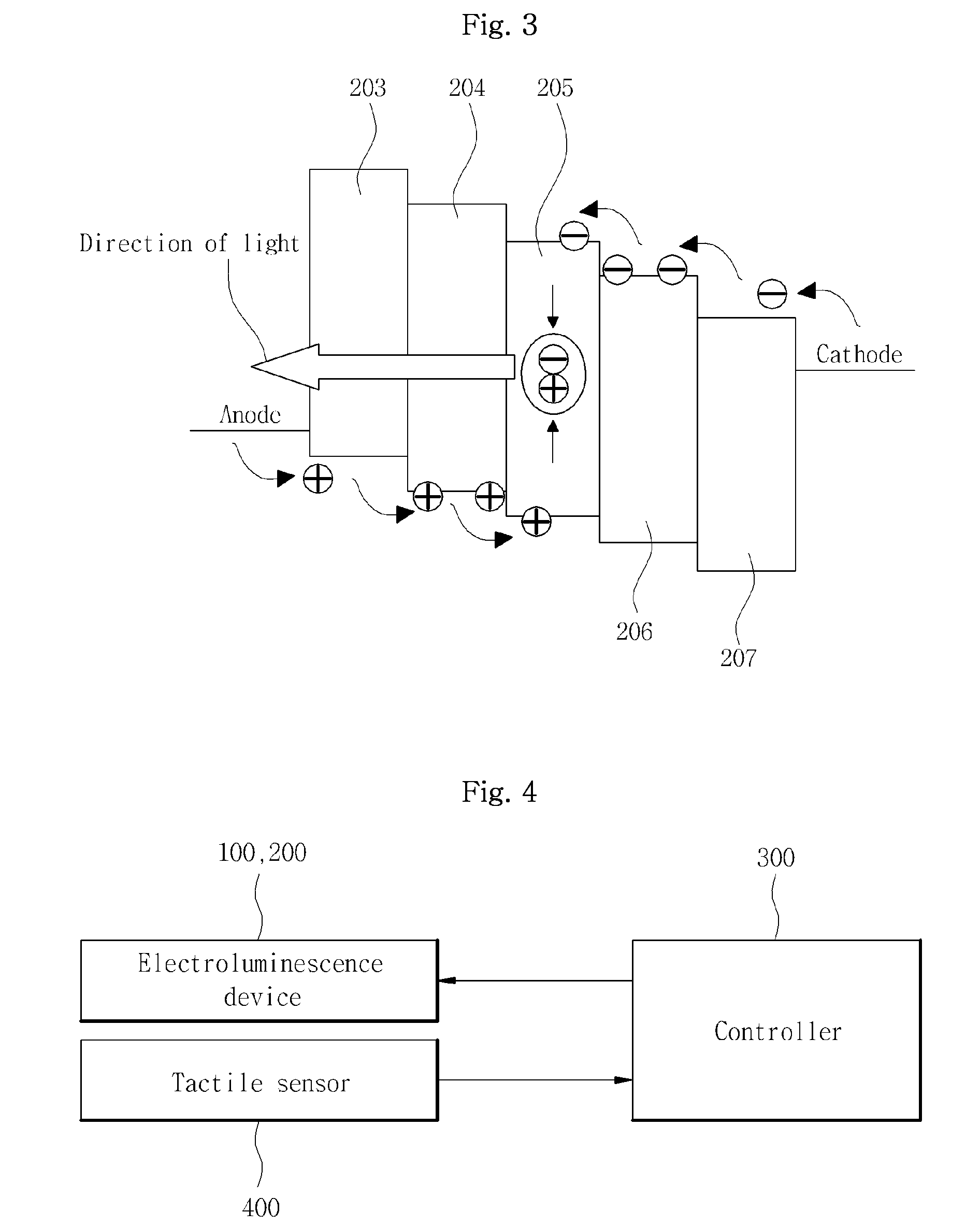
[0052]FIG. 4 is a block diagram of a brightness controllable electroluminescence device according to the present invention. The brightness controllable electroluminescence device includes an inorganic / organic electroluminescence device 100 or 200, a tactile sensor 400 sensing the intensity of force or the intensity of pressure, and a controller 300 controlling brightness.

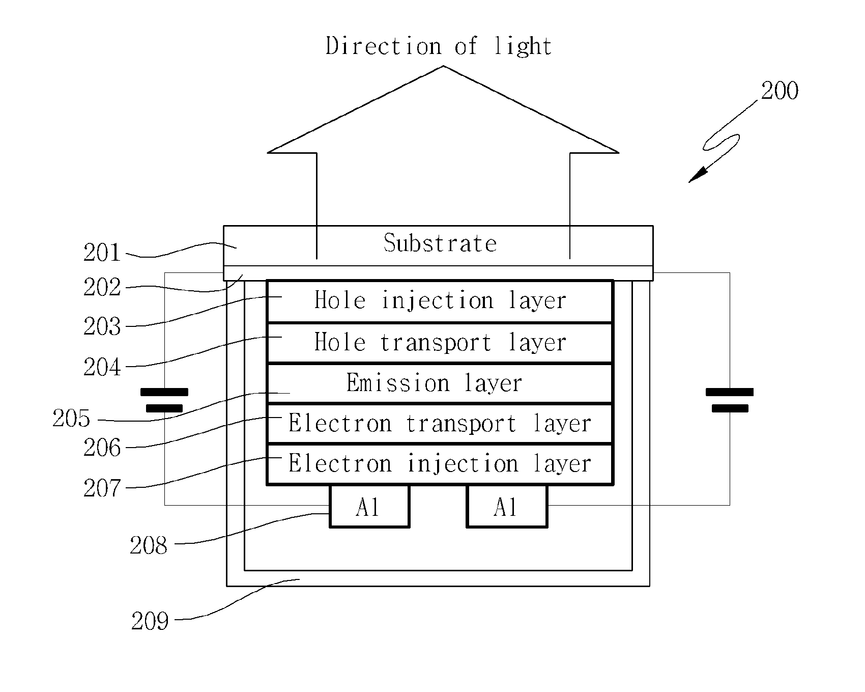
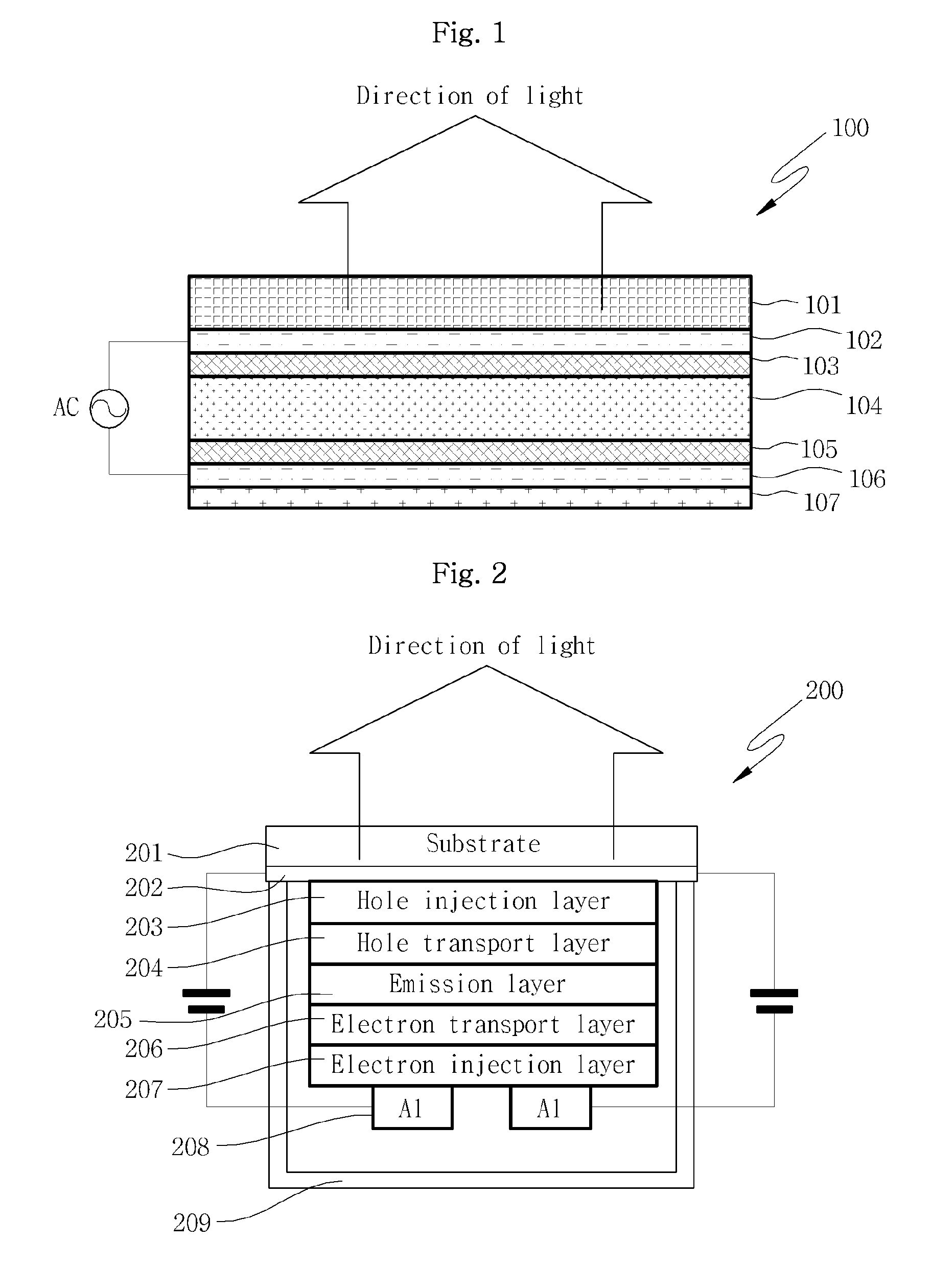
[0053]The inorganic / organic electroluminescence device 100 or 200 may be the inorganic electroluminescence device shown in FIG. 1 or the organic electroluminescence device 200 shown in FIG. 2. In addition, the inorganic / organic electroluminescence device 100 or 200 may be selected from various electroluminescence devices as described above. In all the electroluminescence devices, the quantity of flowing electrons is determined by the intensity of electric field and the extent of emission (brightness) can be changed according to the quantity of flowing electrons.

[0054]The tactile sensor 400 can sense the intensity of...

application examples

[0061]FIG. 8 is a perspective view of a slim cellular phone using a conventional organic electroluminescence device as a keypad lighting device and FIG. 9 is an exploded perspective view of a cellular phone having an organic or inorganic electroluminescence device with the sheet type tactile sensor 400 according to the present invention, which is attached to a keypad of the cellular phone. The cellular phone shown in FIG. 8 has a predetermined brightness irrespective of the intensity of touching force applied to the keypad. In the cellular phone to which the present invention is applied, shown in FIG. 9, touching force or pressure applied to the cellular phone is transferred to the inorganic or organic electroluminescence device 100 or 200 and the tactile sensor 400 located under a keypad cover 2, and thus the brightness can be controlled.

[0062]FIG. 10 is a perspective view showing an organic or inorganic electroluminescence device to which a tactile sensor 510 in the form of a shee...


PUM


Abstract

Disclosed herein is an electroluminescence device capable of controlling the brightness thereof based on the intensity of force or the intensity of pressure. The electroluminescence device includes a substrate at least a part of which is transparent; a first electrode formed on the bottom face of the substrate; an emission layer formed underneath the first electrode; a second electrode formed underneath the emission layer; a tactile sensor formed underneath the second electrode and sensing the intensity of force or the intensity of pressure; and a controller connected to the tactile sensor and adjusting a variation in electric field between the first and second electrodes based on the output of the tactile sensor to control the brightness of light emitted from the emission layer.

Description

BACKGROUND OF THE INVENTION[0001]1. Field of the Invention[0002]The present invention relates to control of the brightness of an electroluminescence device used for a display apparatus or a mobile terminal keypad. More particularly, the invention relates to a brightness controllable electroluminescence device with a tactile sensor sensing the intensity of force or the intensity of pressure.[0003]2. Background of the Related Art[0004]Recently, a variety of flat panel display devices having reduced weights and volumes, different from a cathode ray tube (CRT) having considerable weight and volume, have been developed. These flat panel display devices include a liquid crystal display (LCD), a field emission display, a plasma display panel and an electroluminescence display device.[0005]Among the flat panel display devices, the electroluminescence display device uses electroluminescence. Although electroluminescence has been actively applied to specific fields such as illumination and ba...

Claims


Application Information

Patent Timeline
Patent Type & Authority Applications(United States)
IPC IPC(8): G06F3/041G09G3/30
CPCG06F3/0416G06F3/0414G06F3/0412G06F3/0447H04M1/22H10K59/40
Inventor KIM, JONG HOKIM, MIN SEOKPARK, YON-KYUKANG, DAE IM
Owner KOREA RES INST OF STANDARDS & SCI
Why Eureka
Try Eureka