Light emitting devices and applications thereof

a technology of light emitting devices and optical components, applied in the direction of fixed installation, lighting and heating apparatus, instruments, etc., can solve the problems of thermal, uniformity, efficiency, form factor limitations, and traditional designs using planar lightguides such as used with lcds, and achieve the effect of increasing the angular width and the angular width of indirect ligh

Active Publication Date: 2010-12-23
CREE INC +2
View PDF90 Cites 76 Cited by
  • Summary
  • Abstract
  • Description
  • Claims
  • Application Information

AI Technical Summary

Benefits of technology

[0049]FIG. 37 is a cross-sectional side view of a double edge-lit direct/indirect light fixture comprising a light extracting volumetric scattering element on the bottom surface of the lightguide depicting the increased angular width of the direct light relative to the indirect light in accordance with one embodiment of this inventio

Problems solved by technology

However, traditional designs using planar lightguides such as used with LCDs ha

Method used


Image

  • Light emitting devices and applications thereof
  • Light emitting devices and applications thereof
  • Light emitting devices and applications thereof

Examples


examples

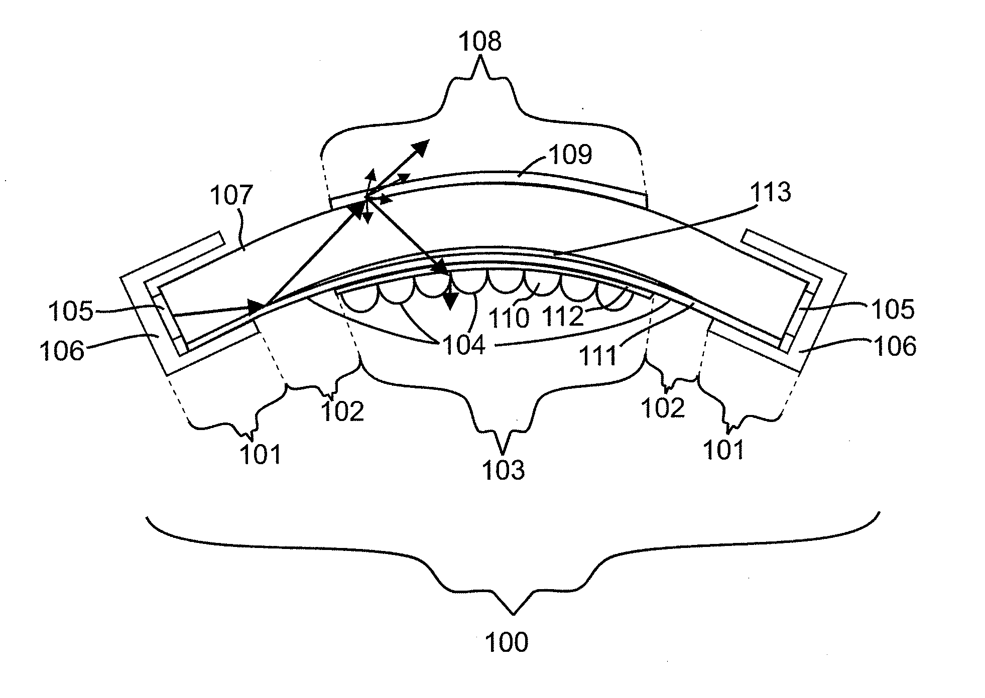
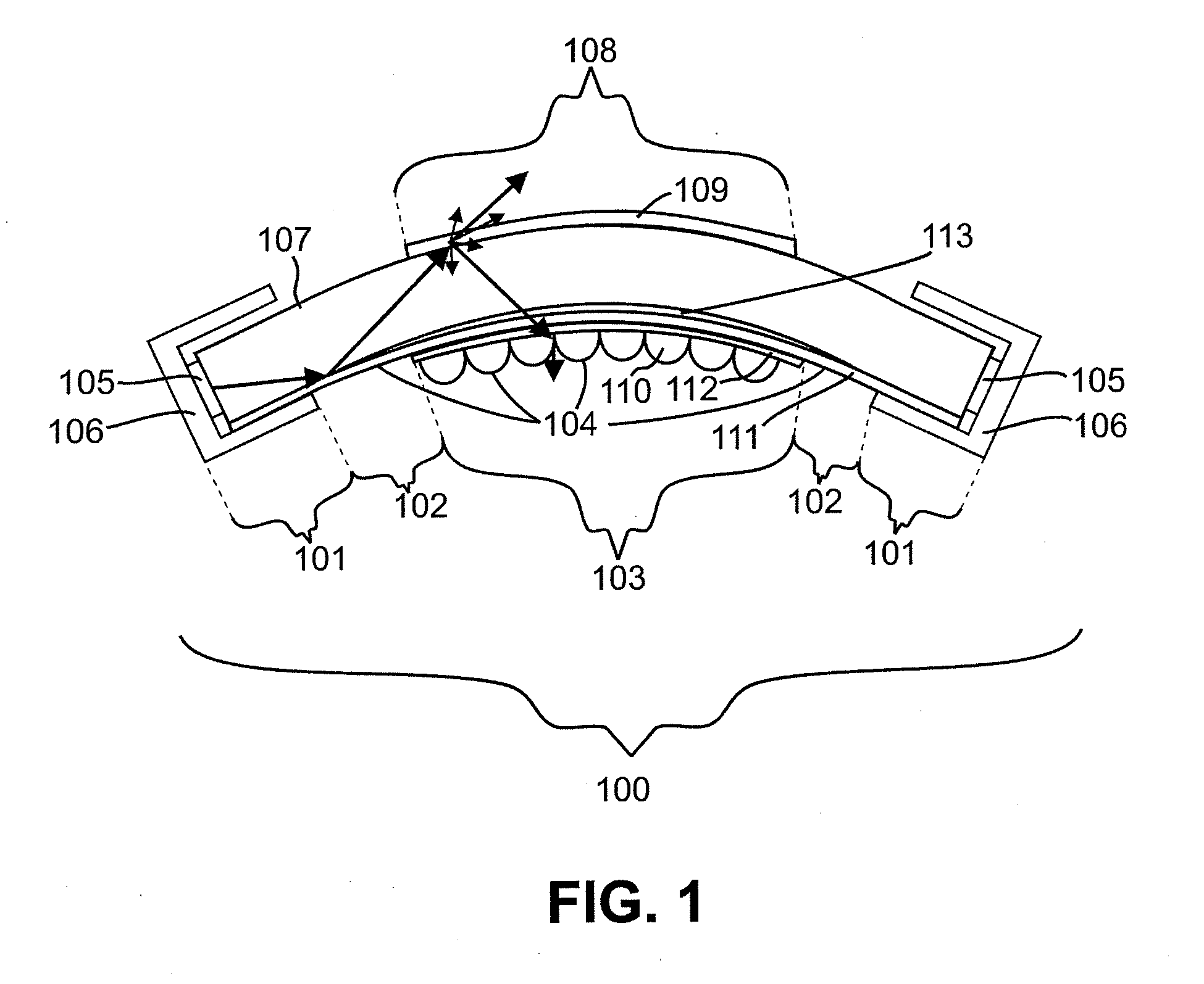
[0208]A light emitting device comprises two linear arrays of light emitting diodes wherein the light from two linear arrays of light emitting diodes is coupled into a curved lightguide with straight segments disposed near the LEDs and substantially within a light blocking region and is illustrated in FIG. 1. The light blocking region reflects a first portion of light from the light emitting diodes, provides mechanical support to the lightguide, obscures light that does not directly couple into the lightguide in a waveguiding condition, and provides thermal transfer properties to conduct heat from the LEDs. The curved lightguide has a light output surface comprising a light emitting region substantially centered within the light output surface. The area of the light emitting region is smaller than the output surface of the lightguide and has a non-scattering light transmitting region disposed between the light emitting region and the light blocking region. The light extracting region...


PUM


Abstract

In one aspect, the present invention provides light emitting devices, including light fixtures and luminaires. In some embodiments, a light emitting device comprises at least one light source, a lightguide operable to receive light from the at least one light source at a first location on the lightguide, at least one light extraction region optically coupled to the lightguide and a substantially non-scattering region along a portion of the lightguide.

Description

RELATED APPLICATION DATA[0001]The present application hereby claims priority under 35 U.S.C. §119(e) to U.S. Provisional Patent Application Ser. Nos. 61 / 170,038, 61 / 174,693, 61 / 174,784, 61 / 174,815, 61 / 174,831, 61 / 174,849 and 61 / 174,861, each of which is incorporated herein by reference in its entirety.FIELD OF THE INVENTION[0002]This invention generally relates to optical components and light emitting devices comprising optical components for illumination and, in particular, to luminaires of various constructions.BACKGROUND OF THE INVENTION[0003]Edge-illuminated lightguides have been used in backlights for LCDs and more recently for light fixtures. However, traditional designs using planar lightguides such as used with LCDs have angular output, thermal, uniformity, efficiency, and form factor limitations.SUMMARY[0004]In one aspect, the present invention provides light emitting devices. In some embodiments, a light emitting device comprises at least one light source, a lightguide ope...

Claims


Application Information

Patent Timeline
IPC IPC(8): F21V7/22
CPCF21S8/04F21Y2101/02G02B6/0035F21V2200/20G02B6/0063F21S8/06G02B6/0061
Inventor COLEMAN, ZANEZHANG, JOHN X.YI YAN NGAI, PETER
Owner CREE INC
Why Eureka
Try Eureka