
Method and Apparatus for Implementing Control of Multiple Physically Dual Homed Devices

a technology of physical dual homed devices and control methods, applied in the field of communication networks, can solve the problems of excessive maintenance costs, multiple failures of configuration, and high maintenance costs of the cor

Inactive Publication Date: 2010-12-23
RPX CLEARINGHOUSE
View PDF28 Cites 11 Cited by
  • Summary
  • Abstract
  • Description
  • Claims
  • Application Information

AI Technical Summary

Benefits of technology

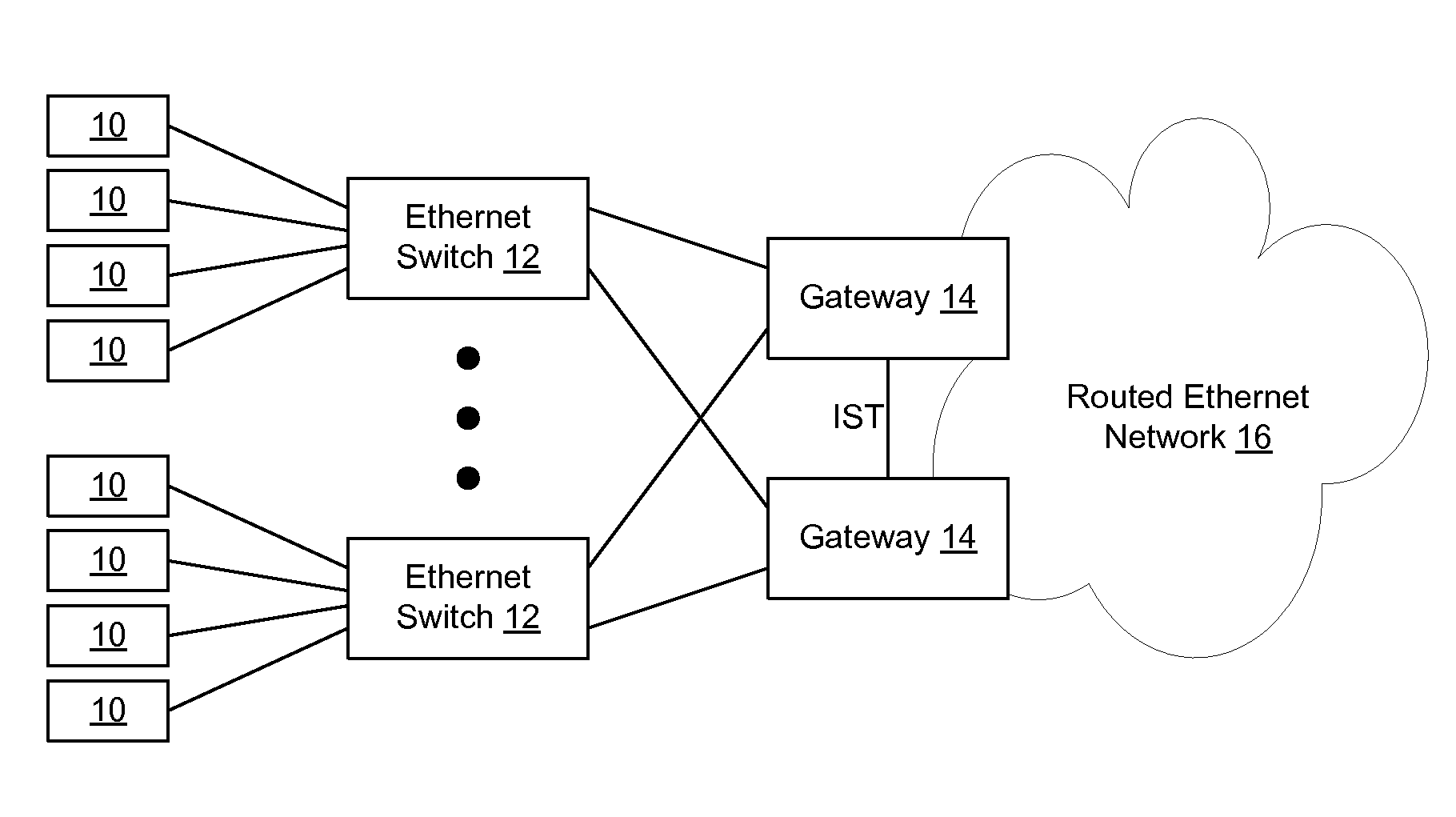
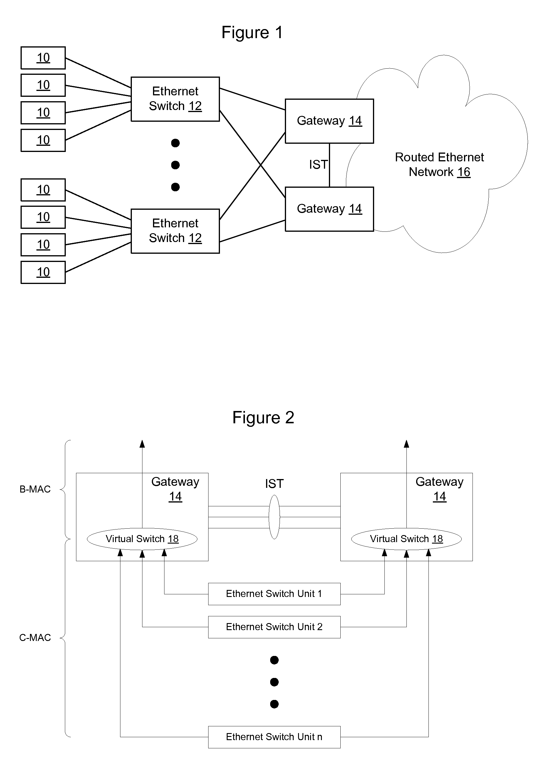
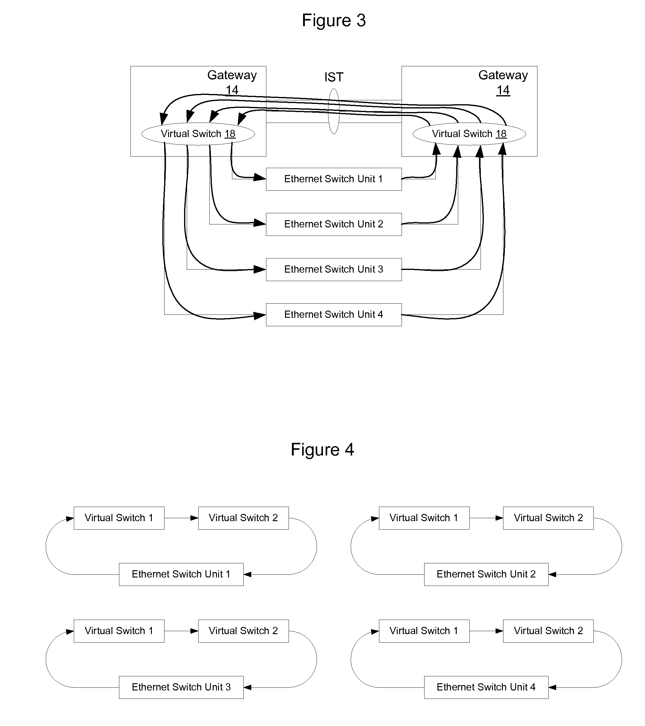
[0009]One or more ring control protocol instances are run on the multiple physically dual homed devices in such a way that enables collections of dual homed devices to be represented by a single pair of addresses into the attached routed Ethernet network. The gateway devices analyze the passing ring control packets to create direct mappings for data packets to the routed Ethernet network. Thus, although the dual homed devices are treated as a ring from a control perspective, the data path is implemented to be direct so that data packets continue to flow directly from the dual homed devices to each of the attached gateway devices. Each of the gateway devices implements one or more virtual switches, which each serve to aggregate traffic from multiple attached ESUs into the routed Ethernet network. Each virtual switch advertises its own MAC address into the routed Ethernet network rather than the MAC addresses of each of the attached Ethernet Switch Units so that fewer MAC addresses will be advertised by each of the gateways. When resiliency is provided for by a peer gateway, frames may be send to and received from the ESU directly or via the peer gateway (in failure scenarios). Frames that are received from the Ethernet switch units are encapsulated at the virtual switch using a new Ethernet header identifying the virtual switch as the source of the data packets. In the reverse direction, frames of data will be addressed to the virtual switch, which will demux packets using the C-MAC Ethernet header to pass the frames onto the correct output port to the correct Ethernet switch unit. By running a separate control plane between the Ethernet switch units and the gateway, a set of Ethernet switch units is able to be represented into the routed Ethernet network using a pair of MAC addresses, while enabling data paths to continue to flow directly between the Ethernet switch units and the routed Ethernet network.

Problems solved by technology

Although it is possible to envision multiple ESUs in a chain connected to a pair of gateway nodes, such a configuration is vulnerable to multiple failures.
Specifically, when the ESU is connected directly to the gateway, the gateway will need to advertise the MAC address of the port via which the ESU is reached into the routed Ethernet network Normally as the number of Ethernet switch units increases, the associated number of ports, and hence the number of MAC addresses being advertised into the routed Ethernet network (e.g. an Ethernet network implemented using 802.1aq Shortest Path Backbone Bridging, although this may also apply to 802.1ah spanning tree controlled Ethernet networks) may become excessive and expensive for the core to maintain.

Method used


Image

  • Method and Apparatus for Implementing Control of Multiple Physically Dual Homed Devices
  • Method and Apparatus for Implementing Control of Multiple Physically Dual Homed Devices
  • Method and Apparatus for Implementing Control of Multiple Physically Dual Homed Devices

Examples


Embodiment Construction

[0018]FIG. 2 is a functional block diagram showing physical dual homed Ethernet switch units interconnecting with a pair of gateway switches. As shown in FIG. 2, each of the Ethernet switch units connects via one or more links to two or more Gateways 14. According to an embodiment, each of the gateways implements at least one virtual switch 18 that summarizes traffic from a plurality of Ethernet switch units into the routed Ethernet network 16. In one embodiment, the virtual switch performs Mac-in-Mac encapsulation to add a B-MAC Ethernet header to the traffic as described in IEEE 802.1ah. Each gateway may implement multiple virtual switches, each of which is responsible for handling traffic for a set of the attached Ethernet switch units. By implementing a virtual switch, sets of subtending ESUs that have a common peer gateway may be represented by a single MAC address into the routed Ethernet network rather than requiring each ESU to be individually represented into the routed Eth...


PUM


Abstract

A ring control protocol is used to establish a separate control plane for a plurality of physically dual homed devices to enable collections of dual homed devices to be represented by a single pair of addresses into the attached routed Ethernet network. The gateway devices analyze the passing ring control packets to create direct mappings for data packets to the routed Ethernet network. Thus, although the dual homed devices are treated as a ring from a control perspective, the data path is implemented to be direct so that data packets continue to flow directly from the dual homed devices to each of the attached gateway devices. In one embodiment, each of the gateway devices implements a virtual switch and advertises the MAC address of the virtual switch into the routed Ethernet network rather than the MAC addresses of each of the attached Ethernet Switch Units.

Description

TECHNICAL FIELD[0001]The present invention relates to communication networks and, more particularly, to a method and apparatus for implementing control of multiple physically dual homed devices.BACKGROUND[0002]Data communication networks may include various switches, routers, hubs, and other devices coupled to and configured to receive data and forward the data on the network. These devices will be referred to herein as “network elements.” A network element is generally not a consumer of the data, but rather is used to receive and forward data so that the data may pass through the network. Data is communicated through a network by enabling the network elements to pass protocol data units, such as frames, packets, cells or segments, between each other over communication links. A particular protocol data unit may be handled by multiple network elements and cross multiple communication links as it travels between its source and its destination over the network.[0003]The various network...

Claims


Application Information

Patent Timeline
IPC IPC(8): H04L12/28
CPCH04L45/66H04L49/351H04L41/0672H04L12/437H04L49/70A61K31/337A61K33/00A61K47/12H04L41/0668H04L45/28H04L41/0661
Inventor ALLAN, DAVIDASHWOOD SMITH, PETER
Owner RPX CLEARINGHOUSE
Learn More