Systems and methods for 3-d target location

a technology of target location and system, applied in the field of system and method for remote three-dimensional target location, can solve the problem that the observer cannot see in 3-d

Active Publication Date: 2010-12-23
EYEGAZE INC
View PDF6 Cites 60 Cited by
  • Summary
  • Abstract
  • Description
  • Claims
  • Application Information

AI Technical Summary

Problems solved by technology

A key limitation of current remote display systems is that the observer cannot see in 3-D.

Method used


Image

  • Systems and methods for 3-d target location
  • Systems and methods for 3-d target location
  • Systems and methods for 3-d target location

Examples


Embodiment Construction

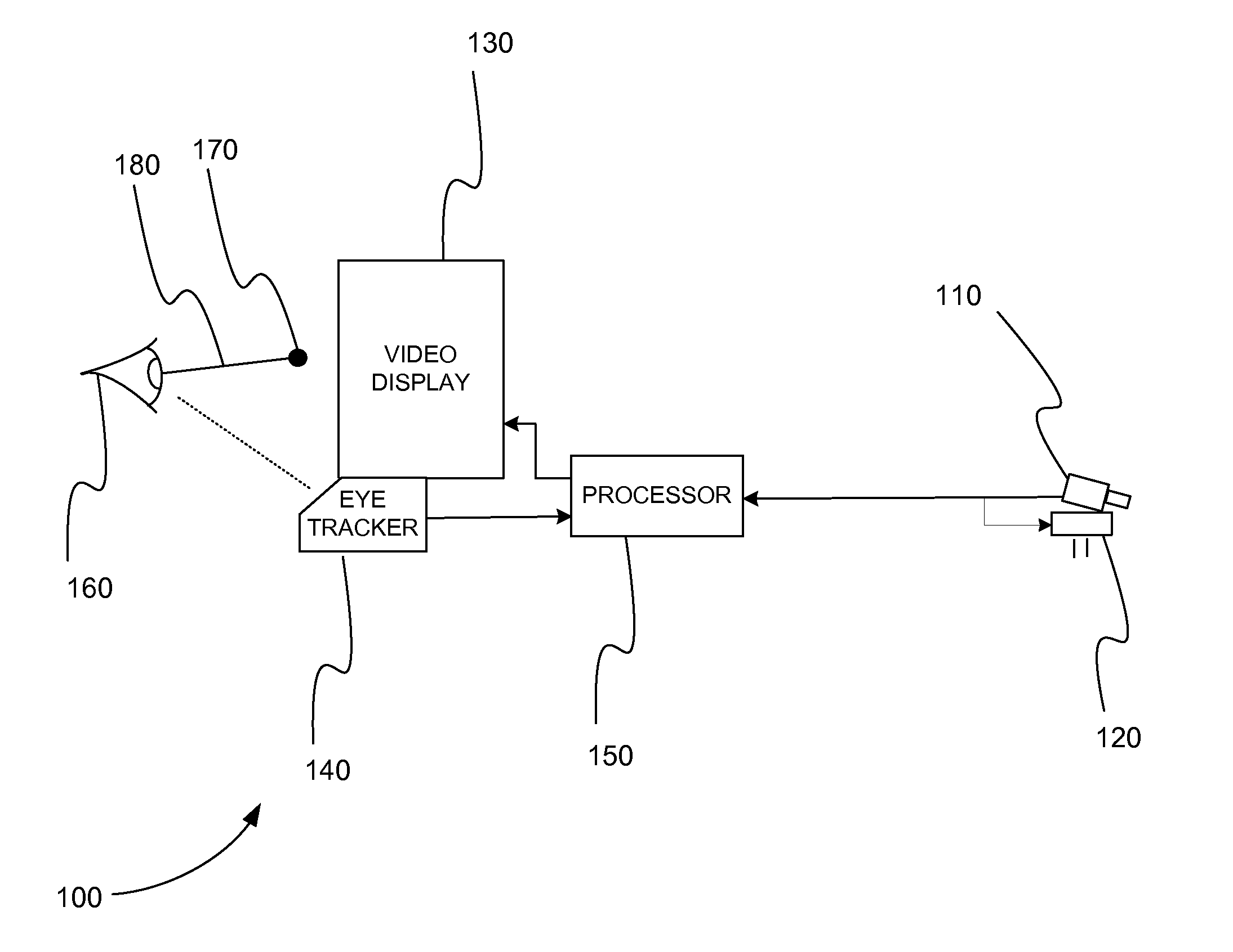
Remote Camera Control

[0016]As described above, a robot operator must control multiple robotic systems simultaneously. Traditionally, a robot operator has used his hands to control all of these systems. In various embodiments, systems and methods provide a robot operator means to control remote vision systems without using his hands, which are typically occupied in controlling the robot itself. When using remote vision in robotic applications, it is often desirable for the operator to be able to control the robot vision system as if he were controlling his own eyes at the scene.

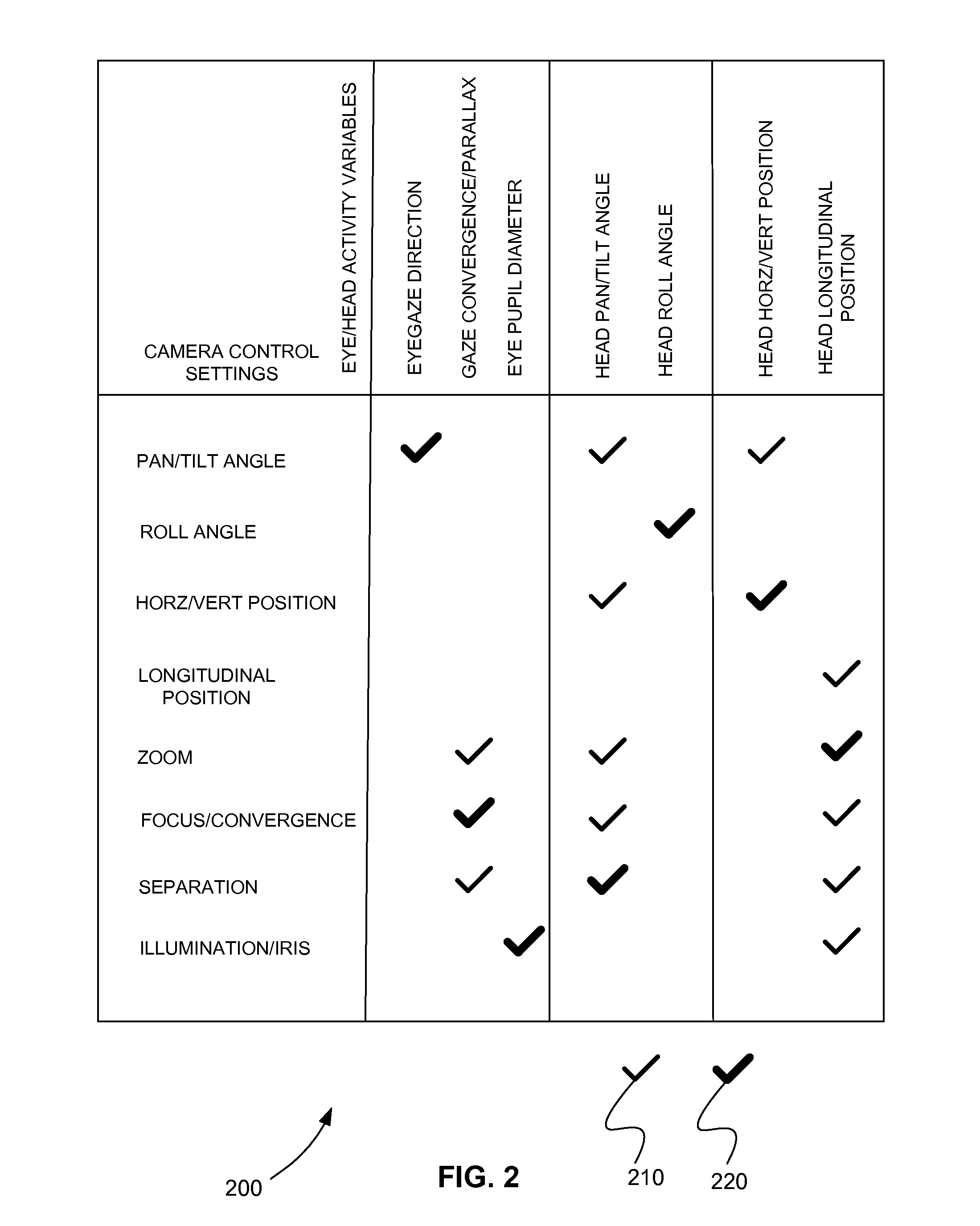
[0017]In various embodiments, a camera's pan and tilt angles are manipulated in direct response to the operator's own eye orientations. In this manner, the camera automatically rotates to point directly toward the object the operator is looking at on his display screen. Additionally, eye and / or head movements may be used to direct other camera activity such as camera roll; zoom; x, y and z position with respec...


PUM


Abstract

A target is imaged in a three-dimensional real space using two or more video cameras. A three-dimensional image space combined from two video cameras of the two or more video cameras is displayed to a user using a stereoscopic display. A right eye and a left eye of the user are imaged as the user is observing the target in the stereoscopic video display, a right gaze line of the right eye and a left gaze line of the left eye are calculated in the three-dimensional image space, and a gazepoint in the three-dimensional image space is calculated as the intersection of the right gaze line and the left gaze line using a binocular eyetracker. A real target location is determined by translating the gazepoint in the three-dimensional image space to the real target location in the three-dimensional real space from the locations and the positions of the two video cameras using a processor.

Description

CROSS-REFERENCE TO RELATED APPLICATION[0001]This application claims the benefit of U.S. Provisional Patent Application No. 61 / 187,864 filed Jun. 17, 2009.INTRODUCTION[0002]1. Field of the Invention[0003]Embodiments of the present invention relate to systems and methods for remote three-dimensional target location. More particularly, embodiments of the present invention relate to systems and methods for remotely determining the location of a target in a three-dimensional real space by tracking the eyes of user viewing a stereoscopic image of the target in a three-dimensional image space.[0004]2. Background Information[0005]A key goal in modern arthroscopic surgery is to allow the surgeon to identify the three-dimensional (3-D) location of objects he cannot see directly. A key goal of future combat systems is to keep a soldier out of harm's way. It is desirable to let a soldier fight from far away, while giving him all the information he would get if he were close in. Remote video sen...

Claims


Application Information

Patent Timeline
Patent Type & Authority Applications(United States)
IPC IPC(8): G06K9/00H04N13/02
CPCG06F3/012G06F3/013G06F3/0325H04N5/23296H04N5/23293H04N5/247H04N7/185H04N5/23203H04N13/239H04N13/296H04N13/383H04N23/66H04N23/61H04N23/63H04N23/695H04N23/90H04N23/611H04N23/56H04N23/69H04N5/57
Inventor CLEVELAND, DIXON
Owner EYEGAZE INC
Why Eureka
Try Eureka