Recording medium, playback device, and integrated circuit

a technology of playback device and recording medium, applied in the field of stereoscopic video playback, can solve problems such as the reduction of buffer capacity, and achieve the effect of reducing the buffer capacity necessary

Active Publication Date: 2010-03-18
PANASONIC CORP
View PDF3 Cites 55 Cited by
  • Summary
  • Abstract
  • Description
  • Claims
  • Application Information

AI Technical Summary

Benefits of technology

[0011]There are optical discs having a plurality of recording layers such as a dual layer disc. With such an optical disc, a series of AV stream files may be recorded on disc areas extending over two layers. Even with a single layer disc, in addition, a series of AV stream files may be recorded on separate areas between which a different file is recorded. In such cases, the optical pickup of an optical disc drive needs to execute a focus jump or a track jump in data reading from the optical disc. The focus jump is a jump caused by a layer switching, and the track jump is a jump caused by a movement of the optical pickup in a radial direction of the optical disk. Generally, these jumps involve longer seek time, thus called long jumps. Ensuring seamless video playback regardless of a long jump needs the extent accessed immediately before the long jump to have a large size enough to satisfy the condition for preventing buffer underflow in a video decoder during the long jump.
[0012]In order to satisfy the above-mentioned condition in both 2D and 3D video playback when the 2D / left-view AV stream file and the right-view AV stream file are arranged in an interleaved manner as shown in FIG. 59, however, the area accessed immediately before the long jump needs to have a larger size of an extent of the right-view AV stream file in addition to a sufficiently larger size of the extent of the 2D / left-view AV stream since both the extents have the same playback time. As a result, a 2D / 3D playback device needs to allocate a larger buffer capacity to a right video decoder, the buffer capacity larger than that satisfying the above-mentioned condition. This is not desirable since it prevents further reduction in buffer capacity and further improvement in memory efficiency of a playback device.
[0013]An object of the present invention is to provide a recording medium having stream files recorded thereon in an arrangement to allow further reduction in the buffer capacity necessary for stereoscopic playback.
[0015]When video images are played back from the recording medium according to the present invention described above, the stereoscopic specific area is accessed immediately before a long jump occurring in stereoscopic playback, whereas the monoscopic specific area is accessed immediately before a long jump occurring in monoscopic playback. Thus, the playback path for stereoscopic playback and the playback path for monoscopic playback are separated immediately before their respective long jumps. This allows the extent sizes of the stream files arranged on the stereoscopic specific area to be determined regardless of the extent size of the base-view stream file arranged on the monoscopic specific area. Especially, sizes and an arrangement of extents recorded on the stereoscopic specific area are allowed to be designed to satisfy only the condition for seamless playback of stereoscopic video images. Independently of that, sizes and an arrangement of extents recorded on the monoscopic specific area are allowed to be designed to satisfy only the condition for seamless playback of monoscopic video images. As a result, further reduction in the buffer capacity necessary for stereoscopic playback can be achieved.

Problems solved by technology

This is not desirable since it prevents further reduction in buffer capacity and further improvement in memory efficiency of a playback device.

Method used


Image

  • Recording medium, playback device, and integrated circuit
  • Recording medium, playback device, and integrated circuit
  • Recording medium, playback device, and integrated circuit

Examples


first embodiment

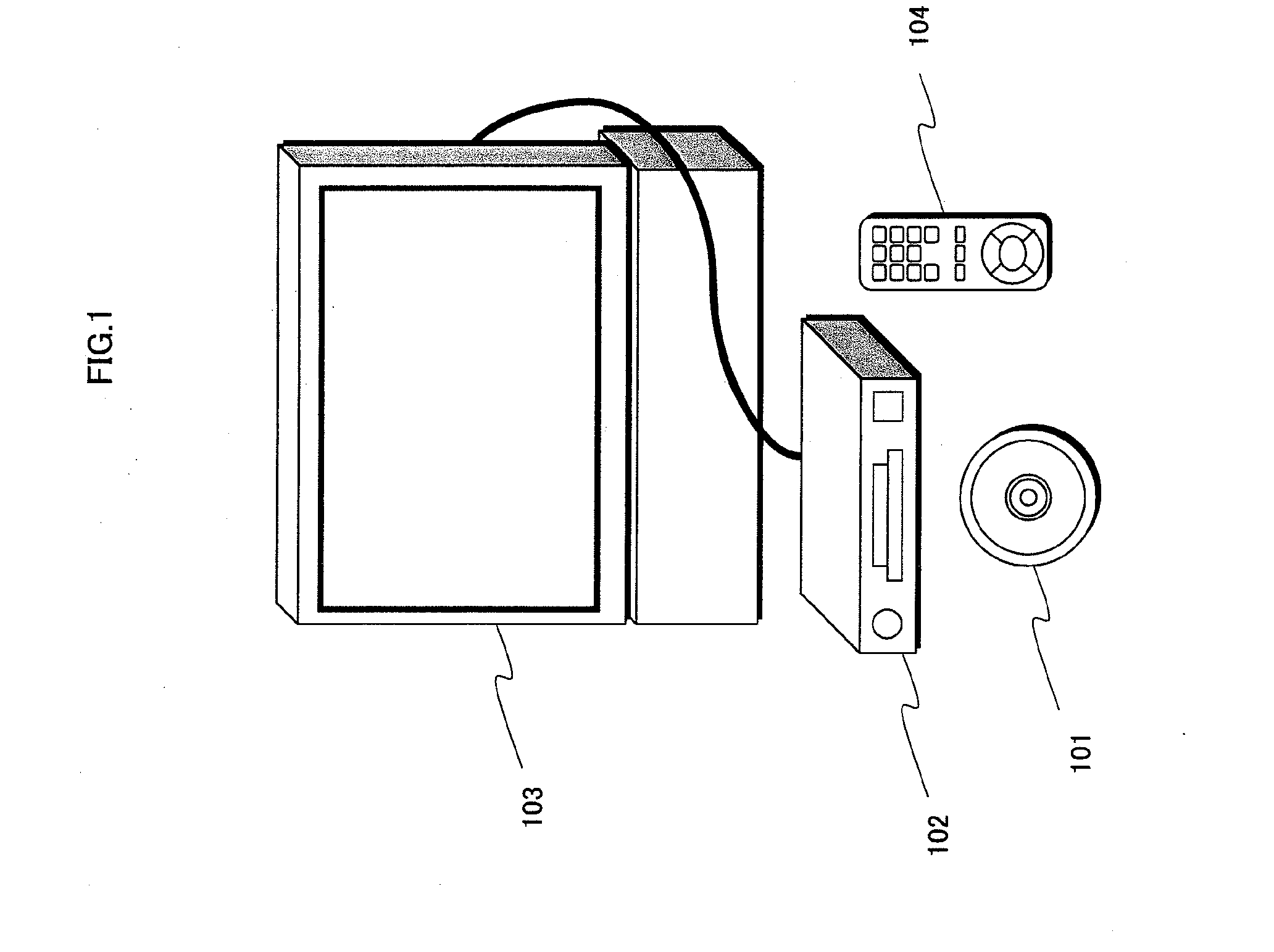
[0078]First, the following describes a usage pattern of a recording medium in accordance with a first embodiment of the present invention. FIG. 1 is a schematic diagram showing a usage pattern of the recording medium. In FIG. 1, a BD-ROM disc 101 is depicted as the recording medium. A playback device 102, a display device 103, and a remote control 104 constitute one home theater system. The BD-ROM disc 101 provides movies to the home theater system.

[0079]Of the BD-ROM disc 101, which is the recording medium pertaining to the first embodiment of the present invention, the data structure relating to the storage of 2D video images is described next.

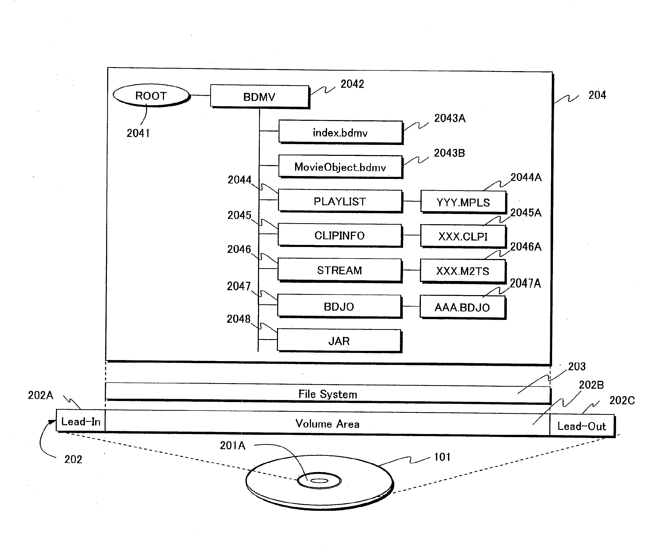
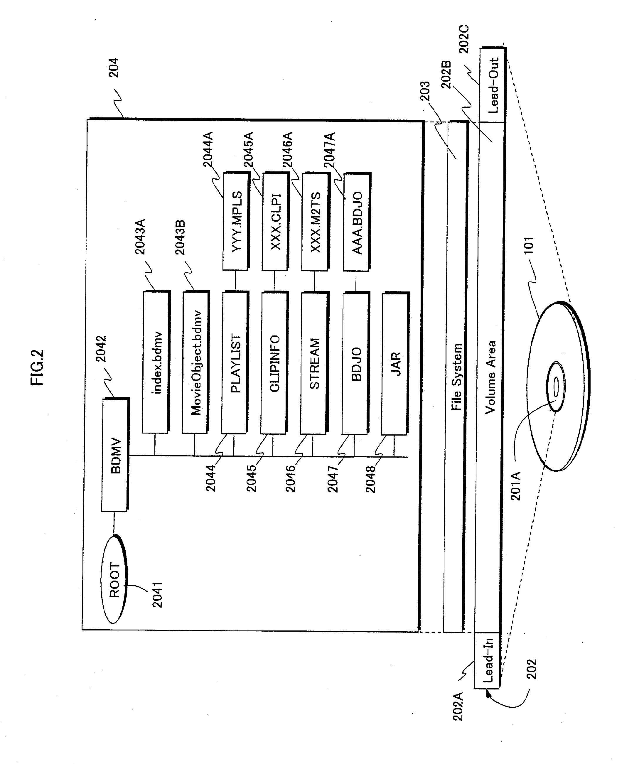
[0080]FIG. 2 is a schematic diagram showing the data structure of the BD-ROM disc 101. On the BD-ROM disc 101, a track 202 is formed spiraling from the inner to outer circumference of the BD-ROM disc 101, as with DVDs and CDs. In FIG. 2, the track 202 is virtually extended in a transverse direction. The left side of FIG. 2 represents the inn...

second embodiment

[0321]The recording medium according to the second embodiment differs that according to the first embodiment in an arrangement of extents in the recording areas to be accessed immediately before / after a long jump. Other features of the second embodiment such as the data structure of the recording medium and the configuration of the playback device are similar to those of the first embodiment. Accordingly, the following will describe the features of the second embodiment different from those of the first embodiment. The explanation about the features of the second embodiment similar to those of the first embodiment can be found the explanation about the first embodiment.

[0322]FIGS. 53A and 53B are schematic diagrams showing the arrangements of extents in the recording areas on the discs of the first and second embodiments, respectively. The recording areas are to be accessed before and after a long jump. Like FIG. 51, each of FIGS. 53A and 53B shows that a series of AV stream files i...

third embodiment

[0328]The recording medium according to the third embodiment differs that according to the first embodiment in the arrangements of extents in the recording area (s) to be accessed immediately before a long jump. Other features of the third embodiment such as the data structure of the recording medium and the configuration of the playback device are similar to those of the first embodiment. Accordingly, the following will describe the features of the third embodiment different from those of the first embodiment. The explanation about the features of the third embodiment similar to those of the first embodiment can be found in the explanation about the first embodiment.

[0329]FIG. 54 is a schematic diagram showing the arrangements of extents in the recording area (s) on the disc of the third embodiment. The recording area (s) is to be accessed immediately before a long jump. Like FIG. 51, FIG. 54 shows that a series of AV stream files is divided into a first 3D extent block 5401 and a ...


PUM

PropertyMeasurementUnit
jump time Tjump-maxaaaaaaaaaa
playback timeaaaaaaaaaa

Abstract

On a recording medium, stereoscopic and monoscopic specific areas are located one after another next to a stereoscopic / monoscopic shared area. The stereoscopic / monoscopic shared area is a contiguous area to be accessed both in stereoscopic video playback and monoscopic video playback. The stereoscopic specific area is a contiguous area to be accessed immediately before a long jump occurring in stereoscopic video playback. In both the stereoscopic / monoscopic shared area and the stereoscopic specific area, extents of base-view and dependent-view stream files are arranged in an interleaved manner. The extents on the stereoscopic specific area are next in order after the extents on the stereoscopic / monoscopic shared area. The monoscopic specific area is a contiguous area to be accessed immediately before a long jump occurring in monoscopic video playback. The monoscopic specific area has a copy of the entirety of the extents of the base-view stream file recorded on the stereoscopic specific area.

Description

BACKGROUND OF THE INVENTION[0001](1) Field of the Invention[0002]The present invention relates to a technology for stereoscopic video playback and especially to the allocation of a video stream on a recording medium.[0003](2) Description of the Related Art[0004]For distribution of moving image contents, optical discs such as DVDs and Blu-ray discs (BDs) are widely used. BDs are with larger capacity compared with DVDs and thus capable of storing high quality video images. Specifically, for example, a DVD is capable of storing standard definition (SD) images at the resolution of 640×480 according to the VGA, and 720×480 according to the NTSC standard. In contrast, a BD is capable of storing high definition (HD) images at the maximum resolution of 1920×1080.[0005]In recent years, there is an increasing number of movie theaters where customers can enjoy stereoscopic (which is also referred to as three-dimensional (3D)) video images. In response to this trend, developments of a technolog...

Claims


Application Information

Patent Timeline
Patent Type & Authority Applications(United States)
IPC IPC(8): H04N5/91H04N7/26G11B20/10G11B20/12H04N5/85H04N5/92H04N5/93H04N5/937H04N13/00H04N13/04
CPCG11B27/105G11B27/3027G11B27/322G11B2020/10629H04N13/0055G11B2220/2541H04N5/85H04N9/8042H04N9/8211G11B2020/10722H04N13/189H04N5/91
Inventor SASAKI, TAIJIYAHATA, HIROSHIOGAWA, TOMOKI
Owner PANASONIC CORP
Why Eureka
Try Eureka