
Method for generating real time tridimensional video based on binocular camera

A binocular camera and stereoscopic video technology, which is applied in the field of intermediate processing and display, and real-time stereoscopic video acquisition, to achieve the effects of reducing workload, facilitating popularization and application, and low cost

Inactive Publication Date: 2008-10-01
TSINGHUA UNIV
View PDF0 Cites 57 Cited by
  • Summary
  • Abstract
  • Description
  • Claims
  • Application Information

AI Technical Summary

Problems solved by technology

[0009] The purpose of the present invention is to propose a real-time stereoscopic video generation method based on binocular cameras in order to overcome the problems existing in the existing method for making stereoscopic video

Method used

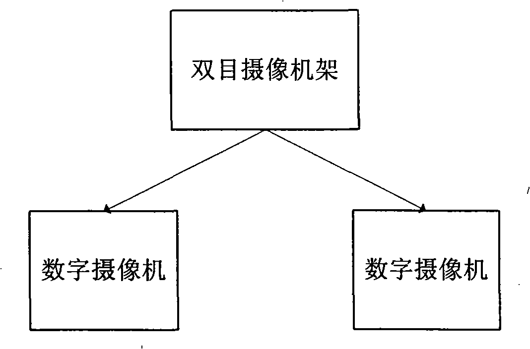

Image

  • Method for generating real time tridimensional video based on binocular camera
  • Method for generating real time tridimensional video based on binocular camera
  • Method for generating real time tridimensional video based on binocular camera

Examples


Embodiment Construction

[0028] A binocular camera-based real-time stereoscopic video generation method proposed by the present invention will be described in detail below with reference to the accompanying drawings and specific embodiments.

[0029] A method for generating a real-time stereoscopic video live broadcast system based on a binocular camera proposed by the present invention, such as figure 2 shown, including the following steps:

[0030] 1) Calibration: Obtain the geometric parameters of the binocular camera, including internal parameters and external parameters;

[0031] 2) Acquisition: Use a binocular camera to synchronously acquire the left view and the right view to form two synchronous videos;

[0032] 3) Correction: According to the outer pole constraints, the geometric parameters of the binocular camera are used to process the two channels of video collected frame by frame, so that the corresponding pixels in each pair of synchronously collected left and right views are located i...


PUM


Abstract

The invention relates to a real-time three-dimensional video generation method that belongs to the acquisition and processing technology field of the three-dimensional video. The method involves the following steps of calibration, collection, regulation, stereo match, virtual view generation and three-dimensional view synthesis. The invention is convenient, simple and rapid, particularly suitable for some situations needing real-time processing.

Description

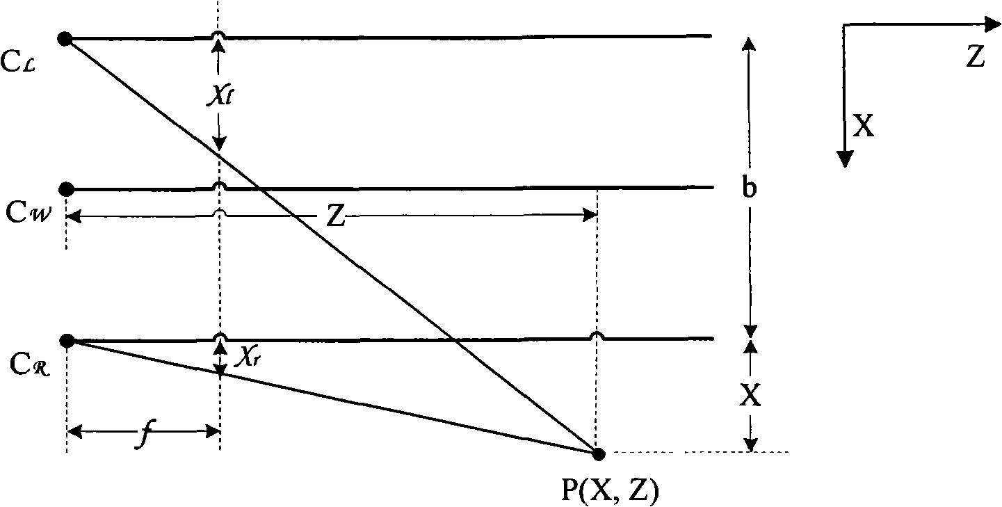
technical field [0001] The invention belongs to the technical field of stereoscopic video acquisition and processing, and in particular relates to a technology of real-time stereoscopic video acquisition, intermediate processing and display based on the principle of binocular stereo vision. Background technique [0002] Binocular stereo vision (binocular stereo vision) is an important branch of computer vision. Its purpose is to collect three-dimensional scenes through translation or rotation of two cameras located in different positions or one camera, and obtain the three-dimensional geometry of the scene after processing. information. [0003] The principle of common binocular stereo imaging is as follows: figure 1 As shown, two cameras C L and C R The optical axes are parallel to each other, their imaging planes coincide with each other, and they are located in the world coordinate system C W on the same XOY plane, and the two cameras have the same focal length f. P(...

Claims


Application Information

Patent Timeline
Patent Type & Authority Applications(China)
IPC IPC(8): H04N13/00H04N15/00
Inventor 戴琼海徐秀兵
Owner TSINGHUA UNIV
Learn More