Earthquake monitoring device

A seismic monitoring and deep-seismic technology, applied in the direction of measuring devices, seismology, optical devices, etc., can solve the problems of high environmental requirements, poor anti-interference ability, expensive equipment, etc., and achieve high degree of automation, strong anti-interference ability, The effect of low manufacturing cost

Inactive Publication Date: 2009-09-23
HUAZHONG UNIV OF SCI & TECH
View PDF0 Cites 48 Cited by
  • Summary
  • Abstract
  • Description
  • Claims
  • Application Information

AI Technical Summary

Problems solved by technology

Ordinary seismic wave monitoring instruments have poor anti-interference ability. As long as there is strong magnetic field or electric field interference, false alarms will occur. If you want to be able to measure accurately, it is required to install it in areas with high environmental requirements such as caves.
[0005] 2. The earthquake is out of bounds
Ordinary seismic wave monitoring instruments have a narrow frequency band, and the outlier phenomenon is common when a major earthquake comes, that is, when the earthquake is greater than a certain level, the magnitude of the earthquake cannot be distinguished on the seismograph
[0006] In the monitoring of earthquake precursors, its implementation relies on various precursor instruments, such as extensometers, inclinometers, gravimeters, borehole strain gauges, etc., which can realize the parameters of earthquake precursors, but the equipment is generally expensive and has high environmental requirements. Poor adaptability, difficult to install, difficult to achieve large-area networking, and difficult to achieve large-area, three-dimensional monitoring of earthquakes

Method used


Image

  • Earthquake monitoring device

Examples


Embodiment Construction

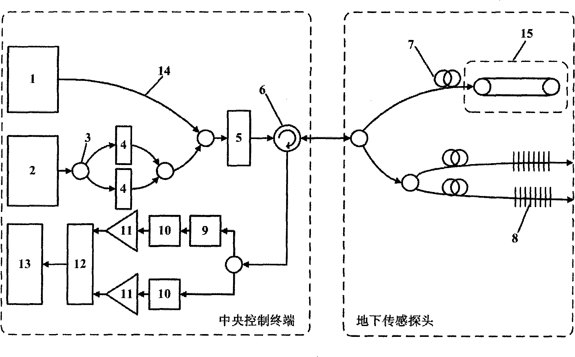
[0019] The earthquake monitoring device provided by the invention is composed of a central control terminal and an underground sensing probe. Among them: the light pulse signal emitted by the light source part of the central control terminal is transmitted to the underground sensing probe located in the deep environment through an optical fiber, and then modulated by deep vibration, strain and temperature in the probe, it becomes Three separate modulated pulse signals in the time domain, these modulated pulse signals are returned to the information demodulation part of the central control terminal for photoelectric conversion, amplification and data processing, and demodulation is completed, so as to realize real-time monitoring of deep vibration, strain and temperature parameters Monitoring and alarming.

[0020] The above-mentioned central control terminal is composed of a light source part and an information demodulation part, and the specific structure is as follows figur...


PUM

PropertyMeasurementUnit
wavelengthaaaaaaaaaa

Abstract

The invention discloses an earthquake monitoring device. The device consists of a central control terminal and a sensor probe under ground, wherein, a light pulse signal is generated from a light source part of the central control terminal, transmitted to the underground sensor probe in an deep ground environment over an optical fiber, then the light pulse signal is changed into 3 discrete modulated pulse signals in time domain after being vibrated, strained and temperature-modulated in the probe in the deep ground, and the modulated pulse signals return to an information demodulation section of the central control terminal for photoelectric conversion, amplification, data processing to complete demodulation, thus realizing real-time monitoring and alarming of parameters of vibration, strain and temperature in the deep ground. The device has the advantages of low production cost, simple installation, high accuracy and good practicability, being convenient to form a network of stations, and realizing stereoscopic multiparameter monitoring on the deep ground environment in a large range.

Description

technical field [0001] The invention relates to a monitoring device, in particular to a device for earthquake monitoring. Background technique [0002] China is located at the intersection of two major seismic belts in the world - the circum-Pacific seismic belt and the Eurasian seismic belt. It is squeezed by the Pacific plate, the Indian Ocean plate and the Philippine Sea plate. The seismic fault zone is very complicated. The tectonic location determines the frequent earthquakes and the severe earthquakes. . The Wenchuan Earthquake that occurred on May 12, 2008 shocked the hearts of every Chinese, and urged scientific and technological workers to promote the development of science and technology better and faster to serve the work of earthquake prevention and disaster reduction. [0003] The traditional earthquake alarm device is composed of vibration or displacement sensors. When the vibration or displacement sensor senses the vibration or deformation of the building dur...

Claims


Application Information

Patent Timeline
Patent Type & Authority Applications(China)
IPC IPC(8): G01V1/00G01V1/18G01H9/00G01B11/16G01K11/32G01K11/3206
Inventor 刘德明孙琪真张国旺李航宇王彦国汤兆星付轶帆
Owner HUAZHONG UNIV OF SCI & TECH
Why Eureka
Try Eureka