
Use of r-1233 in liquid chillers

a technology of chlorotrifluoropropene and liquid chiller, which is applied in the direction of refrigeration components, lighting and heating equipment, other chemical processes, etc., can solve the problem of air being sucked into the equipmen

Active Publication Date: 2010-12-30
ARKEMA INC
View PDF19 Cites 65 Cited by
  • Summary
  • Abstract
  • Description
  • Claims
  • Application Information

AI Technical Summary

Benefits of technology

The present invention is about the use of chloro-trifluoropropenes as refrigerants for liquid chiller systems. These refrigerants were found to be effective and compatible with current chiller lubricants. The preferred chloro-trifluoropropenes are 1-chloro-3,3,3-trifluoropropene and / or 2-chloro-3,3,3-trifluoropropene, and more specifically trans-1-chloro-3,3,3-trifluoropropene. Overall, this invention provides a useful alternative to current refrigerants for liquid chiller systems.

Problems solved by technology

Also, leaks in the system operating at below ambient pressure result in air being sucked into the equipment rather than refrigerant leaking out.

Method used


Image

  • Use of r-1233 in liquid chillers
  • Use of r-1233 in liquid chillers
  • Use of r-1233 in liquid chillers

Examples


example 1

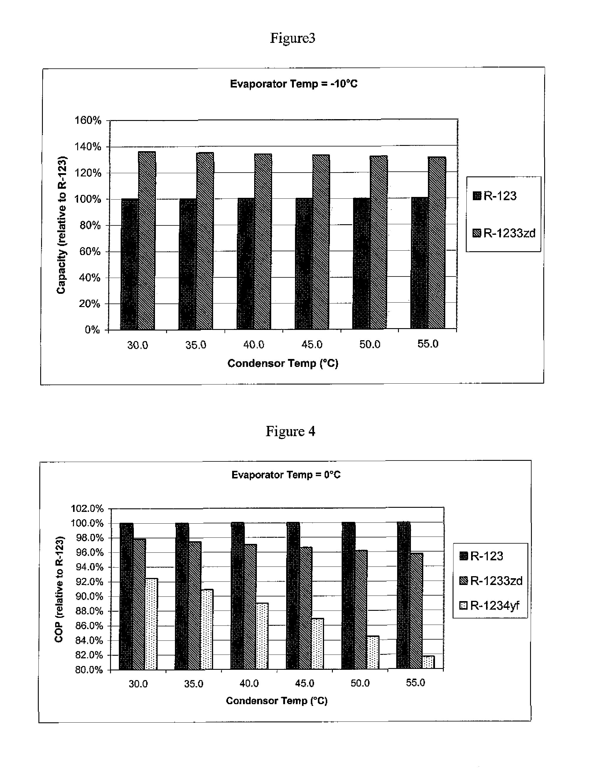
[0053]In this example, the following conditions were used:

[0054]Evaporator temperature=−10° C. Compressor inlet temperature=−5° C. Isentropic efficiency=0.7. The results are tabulated in Table 1.

[0055]FIGS. 2 and 3 show the COP and CAP of R-1233zd and R-1234ze relative to R-123.

TABLE 1T evap −10° C.Internal heat exchangerinlet compressor −5° C.isentropic efficiency 0.7Tcondevap Pcond PP diffP ratioCAP(° C.)(kPa)(kPa)(kPa)(p / p)(KJ / m3)COPR-1234yf30.02197725543.5314563.635.02198826634.0313723.140.021910037854.5812872.745.021911379185.1912002.350.0219128310645.8611112.055.0219144312246.5910191.7R-1233zd30.0281551275.512803.935.0281841566.542693.440.0282171897.712572.945.0282542269.042452.650.02829626810.522332.355.02834331412.182222.1R-12330.020110905.442064.035.0201311116.471993.540.0201551357.661923.145.0201821629.001842.750.02021319210.521772.455.02024722712.231692.2

example 2

[0056]In this example, the following conditions were used:

[0057]Evaporator temperature=0° C. Compressor inlet temperature=5° C. Isentropic efficiency=0.7. The results are tabulated in Table 2.

[0058]FIGS. 4 and 5 show the COP and CAP of R-1233zd and R-1234ze relative to R-123.

TABLE 2T evap 0° C.Internal heat exchangerinlet compressor 5° C.isentropic efficiency 0.7Tcondevap Pcond PP diffP ratioCAP(° C.)(kPa)(kPa)(kPa)(p / p)(KJ / m3)COPR-1234yf30.03127724612.4821525.335.03128825702.8320354.440.031210036913.2219153.745.031211378253.6417933.150.031212839714.1116682.755.0312144311314.6215402.3R-1233zd30.0461551093.374635.635.0461841384.004444.740.0462171714.724264.045.0462542085.534073.550.0462962506.433893.055.0463432977.453702.7R-12330.033110773.363375.735.033131984.003254.840.0331551224.743144.145.0331821495.573023.650.0332131806.512903.155.0332472157.562792.8

example 3

[0059]In this example, the following conditions were used:

[0060]Evaporator temperature=5° C. Compressor inlet temperature=10° C. Isentropic efficiency=0.7. The results are tabulated in Table 3.

[0061]FIGS. 6 and 7 show the COP and CAP of R-1233zd and R-1234ze relative to R-123.

TABLE 3T evap 5° C.Internal heat exchangerinlet compressor 10° C.isentropic efficiency 0.7Tcondevap Pcond PP diffT-outCAP(° C.)(kPa)(kPa)(kPa)comp(KJ / m3)COPR-1234yf30.03687724043926106.735.03688825144524725.440.036810036355123324.445.036811367685621883.7R-1233zd30.05815496445857.035.058183125505625.740.058216158555394.845.058254196615164.1R-12330.04111069444237.235.04113190504095.840.041155114563954.945.041182141613814.2


PUM

PropertyMeasurementUnit
temperatureaaaaaaaaaa
boiling pointaaaaaaaaaa

Abstract

This invention relates to the use of chloro-trifluoropropenes as refrigerants in negative-pressure liquid chillers and methods of replacing an existing refrigerant in a chiller with chloro-trifluoropropenes. The chloro-trifluoropropenes, particularly 1-chloro-3,3,3-trifluoropropene, have high efficiency and unexpectedly high capacity in liquid chiller applications and are useful as more environmentally sustainable refrigerants for such applications, including the replacement of R-123 and R-11.

Description

FIELD OF THE INVENTION[0001]This invention relates to the use of chloro-trifluoropropenes as refrigerants in negative-pressure liquid chillers. The chloro-trifluoropropenes, particularly 1-chloro-3,3,3-trifluoropropene, have high efficiency and unexpectedly high capacity in liquid chiller applications and are useful as more environmentally sustainable refrigerants for such applications, including the replacement of R-123 and R-11. The chloro-trifluoropropenes can be used in new chiller applications or as a top-off or retrofit where the refrigerant is removed from an existing chiller and the chloro-trifluoropropenes of the present invention are added.BACKGROUND OF THE INVENTION[0002]With continued regulatory pressure there is a growing need to identify more environmentally sustainable replacements for refrigerants, heat transfer fluids, foam blowing agents, solvents, and aerosols with lower ozone depleting and global warming potentials. Chlorofluorocarbon (CFC) and hydrochlorofluoroc...

Claims


Application Information

Patent Timeline
Patent Type & Authority Applications(United States)
IPC IPC(8): F25B45/00F25B1/00C09K5/00
CPCC09K5/044C09K2205/126C09K3/30C09K5/045C09K2205/112C09K2205/122C09K2205/32F25B1/005C10M2203/1006C10M2205/028C10M2205/223C10M2207/2835C10M2209/043C10M2209/1033C10N2220/301C10N2220/302C10N2220/303C10N2220/305F25B45/00C10M171/008F25B2400/18F25B1/053F25B1/10F25B9/006C10M2205/0285F25B2339/047F25B31/002C09K2205/40C09K2205/41C10M2203/065C10N2040/30C10N2020/099C10N2020/105C10N2020/103C10N2020/101F25B9/002C10M169/04
Inventor VAN HORN, BRETT L.BONNET, PHILIPPE
Owner ARKEMA INC
Learn More