Transformable structure for producing a multi thread single line stitch and method and machine for its realization

Inactive Publication Date: 2010-12-30
MINGAZHEV ASKAR DZHAMILEVICH +1
View PDF14 Cites 14 Cited by
  • Summary
  • Abstract
  • Description
  • Claims
  • Application Information

AI Technical Summary

Benefits of technology

[0030]The considered stitch line structure consists of a system of several top and several bottom threads joined through the perforations in the material. Such structure provides for a mutual compensation of stretched and squeezed areas of the material and eliminates corrugation of the

Problems solved by technology

Existing at present, chain stitch lines (presented in U.S. Pat. Nos. 3,301,206; 3,753,410) have a limited number of threads (two threads only) being used in the line, and are limited in the variability of the structure of the stitch, which in turn limits the possibilities for adjusting the stitch line structure to the operational requirements.
Likewise, the existing machines, manufacturing two-thread single-line chain stitch lines, have limited functional possibilities (as presented in U.S. Pat. Nos. 3,301,206; 3,753,410; 6,095,069).
The limited number of threads being used in the prior art strongly hinders the potential for changes in the parameters of the stitch, which are limited to changing the step of the stitch and the thread tension.
The contemporary chain stitch line used in sewing knitted goods is not very reliable, and tends to deform the seam, causing corrugation, which creates the appearance of a defect in the finished product.
Another problem in sewing technology is the optimization of stitch line properties along its length.
Thus, although the average properties of the u

Method used


Image

  • Transformable structure for producing a multi thread single line stitch and method and machine for its realization
  • Transformable structure for producing a multi thread single line stitch and method and machine for its realization
  • Transformable structure for producing a multi thread single line stitch and method and machine for its realization

Examples


Example

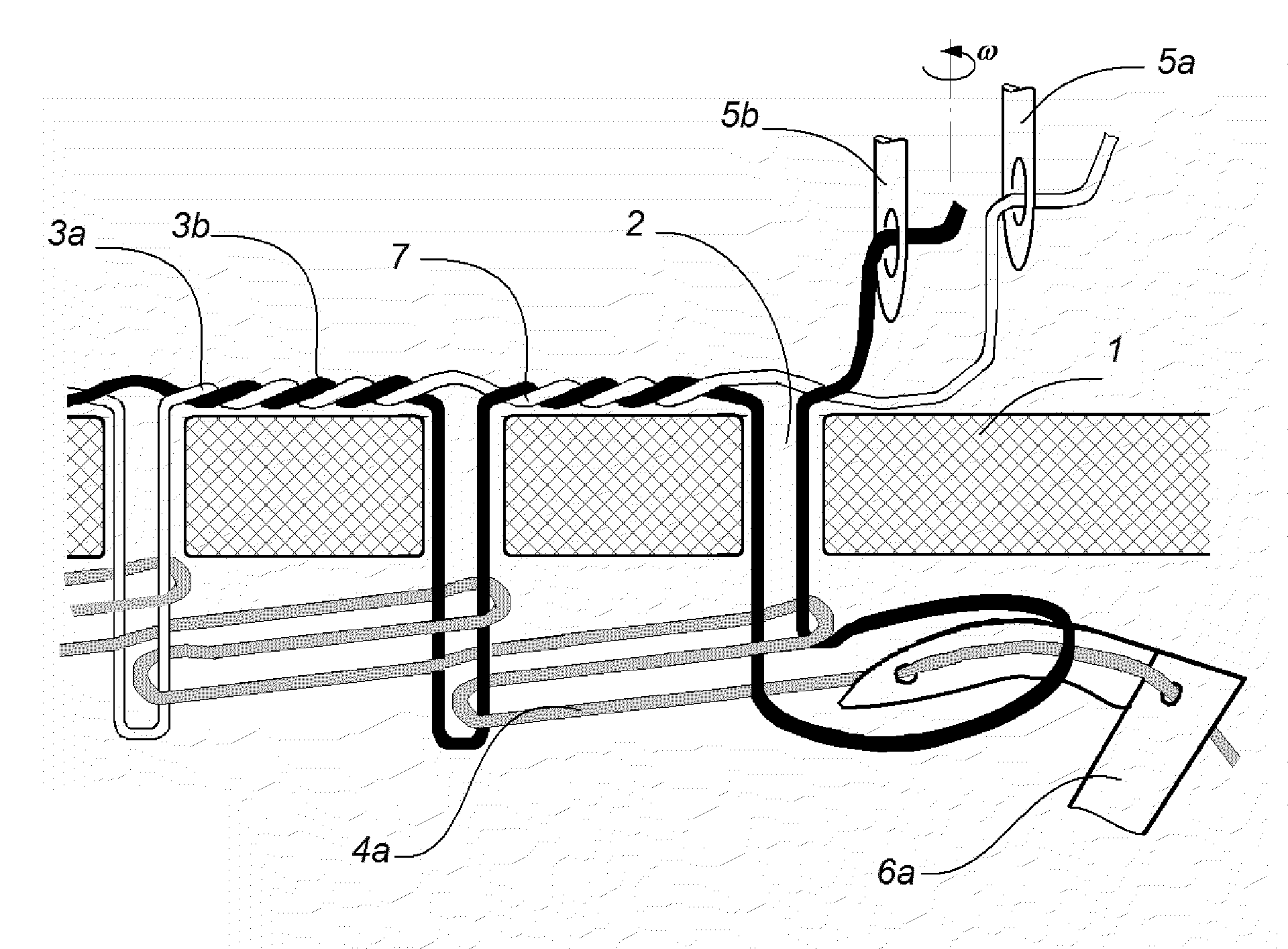
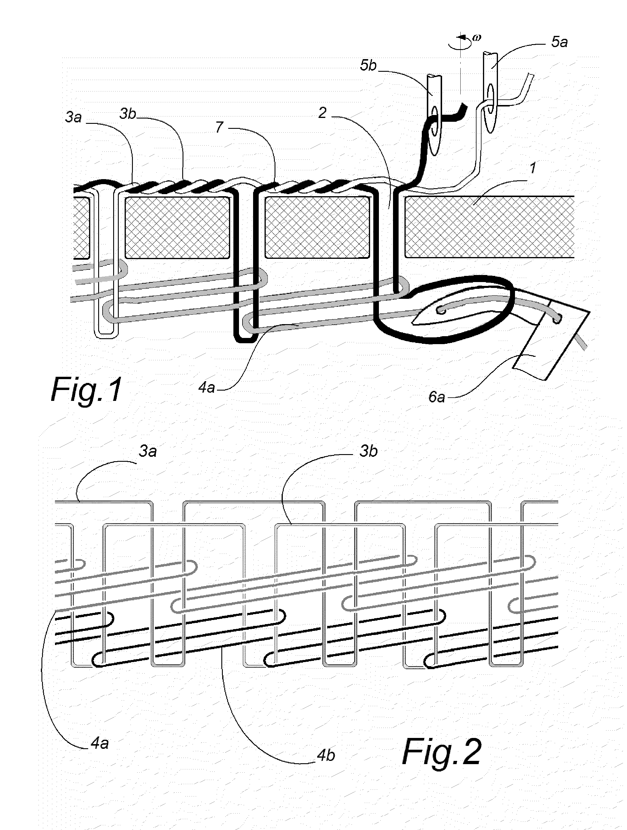
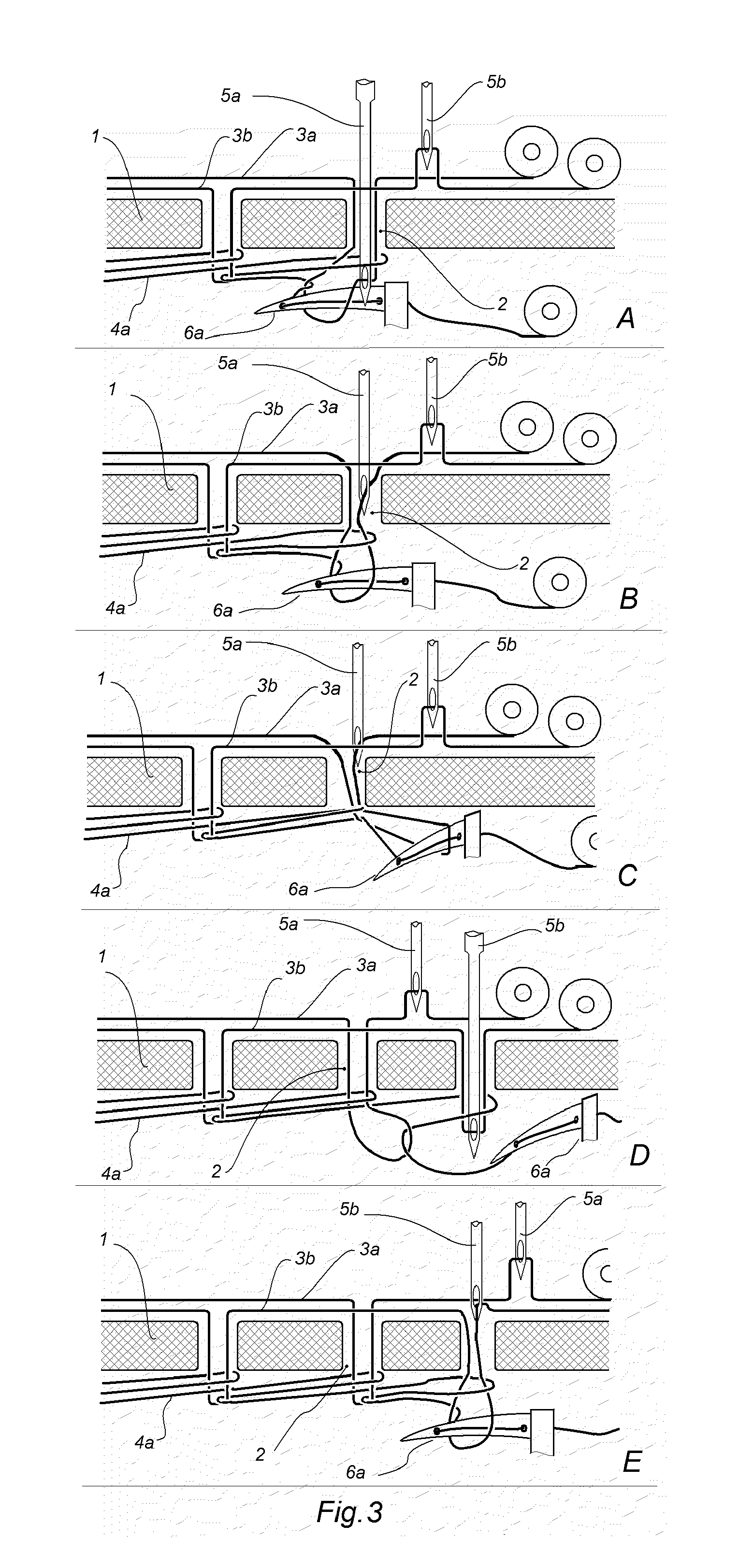
[0066]FIGS. 1-11 disclose: 1—sewn material; 2—perforation; (p#1, p#2, p#3, p#4, p#5—numbers of perforations); 3a—first top thread; 3b—second top thread; 3c—third top thread; 4a—first bottom thread; 4b—second bottom thread; 5a—first top thread needle; 5b—second top thread needle; 5c—third top thread needle; 6a—first bottom thread looper; 6b—second bottom thread looper; 7—thread intertwining; 8—needle unit (needle revolver); 9—looper unit (looper revolver); 10—mechanism for discrete rotation of the needle revolver (e.g. Geneva wheel); 11—mechanism for discrete rotation of the looper revolver (e.g. Geneva wheel); 12—needle bar (12a—first needle bar; 12b—second needle bar); 13—needle bar engaging mechanism; 14—needle bar catching device; 15—needle bar shoulder (15a—first needle bar shoulder; 15b—second needle bar shoulder); 16a—module of needle and thread feeder mechanism of the first needle; 16b—module of needle and thread feeder mechanism of the second needle; 17—bobbin holder with bo...


PUM


Abstract

A multi-thread single-line chain stitch line, consisting of at least three threads. This method provides for the formation of variable structures of stitches, based on varying sequences for the conjoining of several top threads, loaded to their individual needles, with several bottom threads, loaded to their individual loopers. The method suggests intertwining top threads between each other. The proposed stitch structure provides homogeneity of mechanical stresses in the stitch line, resulting in higher strength and durability. The machine to provide such stitch line comprises a revolver, bringing required needles to the operation point and intertwining threads during formation of the stitch line, and likewise comprising a revolver for bringing required loopers to the operation point. In one of the embodiments of the present invention, only three top threads are used, with the looper having no bottom thread loaded in it.

Description

CROSS-REFERENCES TO RELATED APPLICATIONS[0001]Not applicable.STATEMENT REGARDING FEDERALLY SPONSORED RESEARCH AND DEVELOPMENT[0002]Not applicable.BACKGROUND OF THE INVENTION AND RELATED ART STATEMENT[0003]1. Field of the Invention[0004]The present invention relates to the manufacture of equipment for sewing technologies and methods for the sewing industry, the embroidered goods industry, the knitted goods industry, the leather industry and the shoe industry. The present invention comprises a technology for obtaining a multi-thread single-line chain stitch line.[0005]2. Description of Prior Art and Existing Problems[0006]Existing at present, chain stitch lines (presented in U.S. Pat. Nos. 3,301,206; 3,753,410) have a limited number of threads (two threads only) being used in the line, and are limited in the variability of the structure of the stitch, which in turn limits the possibilities for adjusting the stitch line structure to the operational requirements. Likewise, the existing ...

Claims


Application Information

Patent Timeline
IPC IPC(8): D05B1/08D05B57/02
CPCD05B57/02D05B1/08
Inventor MINGAZHEV, ASKAR DZHAMILEVICHPELKEY, BRUCE ALAN
Owner MINGAZHEV ASKAR DZHAMILEVICH
Why Eureka
Try Eureka