Boundary mode coupled inductor boost power converter

a technology of coupled inductor and boost converter, which is applied in the direction of power conversion system, dc-dc conversion, climate sustainability, etc., can solve the problem that the boost converter may not be used in a wide variety of applications, and achieve the effect of eliminating the reverse recovery effect of the rectifier and zero voltage switching

Inactive Publication Date: 2010-12-30
MICROSEMI
View PDF28 Cites 12 Cited by
  • Summary
  • Abstract
  • Description
  • Claims
  • Application Information

AI Technical Summary

Benefits of technology

[0012]Among other things, novel coupled inductor boost circuits are provided that operate in a zero current switching (ZCS) boundary mode and/or a zero voltage switching (ZVS) boundary mode. Some embodiments include a coupled inductor boost circuit that c

Problems solved by technology

While other converter topologies are available, they may often be overlooked.
For example, except in some limited

Method used


Image

  • Boundary mode coupled inductor boost power converter
  • Boundary mode coupled inductor boost power converter
  • Boundary mode coupled inductor boost power converter

Examples


Embodiment Construction

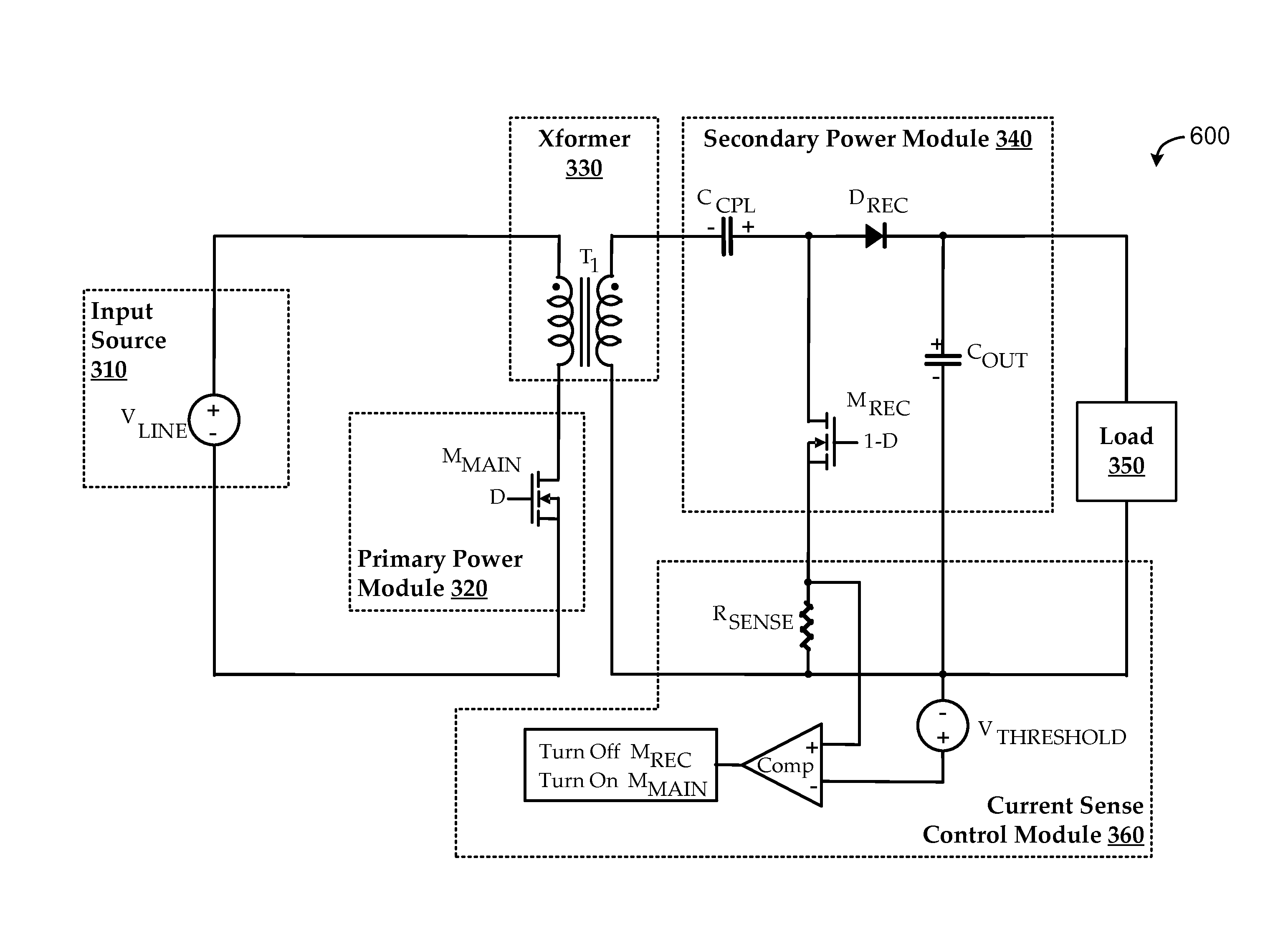
[0037]Embodiments are described herein for providing novel coupled inductor boost circuits that operate in a zero current switching (ZCS) boundary mode and / or a zero voltage switching (ZVS) boundary mode. For example, embodiments manifest improved functionality over typical flyback controller topologies for certain applications, such as in circuit applications where isolation may not be a requirement. Some embodiments include a coupled inductor boost circuit that can substantially eliminate rectifier reverse recovery effects without using a high side primary switch and a high side primary switch driver.

[0038]Other embodiments include a coupled inductor boost circuit that can achieve substantially zero current and / or zero voltage switching. For example, ZCS may be achieved by using a magnetizing inductance sufficiently small that the magnetizing current can drop to zero each cycle. Alternatively, ZVS may be achieved by using a magnetizing inductance sufficiently small that the magnet...


PUM


Abstract

Methods, systems, and devices are described for using coupled inductor boost circuits to operate in a zero current switching (ZCS) and/or a zero voltage switching (ZVS) boundary mode. Some embodiments include a coupled inductor boost circuit that can substantially eliminate rectifier reverse recovery effects without using a high side primary switch and a high side primary switch driver. Other embodiments include a coupled inductor boost circuit that can achieve substantially zero voltage switching. ZCS and ZVS modes may be effectuated using control techniques. For example, a magnetizing current may be sensed or otherwise represented, and a signal may be generated accordingly for controlling switching of the controller.

Description

CROSS-REFERENCES[0001]This applications claims priority from co-pending U.S. Provisional Patent Application No. 61 / 221,049, filed Jun. 27, 2009, entitled “ZERO VOLTAGE SWITCHING BOUNDARY MODE COUPLED INDUCTOR BOOST POWER CONVERTERS”, and co-pending U.S. Provisional Patent Application No. 61 / 221,050, filed Jun. 27, 2009, entitled “BOUNDARY MODE COUPLED INDUCTOR BOOST POWER CONVERTERS”, which are hereby incorporated by reference, as if set forth in full in this document, for all purposes.FIELD[0002]Embodiments generally pertain to electronic power conversion circuits, and, more specifically, to high frequency, switched mode electronic power converters.BACKGROUND[0003]Many typical power converter applications convert power simply and efficiently at low and medium power levels using flyback converters. While other converter topologies are available, they may often be overlooked. For example, except in some limited housekeeping power supplies, coupled inductor boost converters may not be...

Claims


Application Information

Patent Timeline
IPC IPC(8): H02M3/335
CPCH02M3/158Y02B70/1475H02M3/33592H02M3/33576Y02B70/10
Inventor RASKO, GEORGEWITTENBREDER, JR., ERNEST H.
Owner MICROSEMI
Why Eureka
Try Eureka