Multiphase converter with zero voltage switching

a converter and zero voltage technology, applied in the field of dctodc converters and switch mode power supplies, can solve the problems of emi generation, power component stress, switching loss, etc., and achieve the effect of minimizing power loss and zero voltage switching

Active Publication Date: 2005-07-21
INTERSIL INC
View PDF4 Cites 21 Cited by
  • Summary
  • Abstract
  • Description
  • Claims
  • Application Information

AI Technical Summary

Benefits of technology

[0011] In accordance with the present invention, the inductor at the front end does not allow the current to increase until a MOSFET is fully ON. There is no overlapping of current until the MOSFET turns ON. As to the inductor, its transition is smoother and the diode is slowly turning OFF instead of switching. Thus, it can be seen that there is zero current across the upper MOSFET and zero voltage across the lower MOSFET. The inductor resonates with any capacitors of the upper MOSFET's. Because of the resonant tank circuit, the time ON is fixed, but the time ON can vary according to what the controller signals. A total period for each phase is changing and time is variable, notably because the time ON is variable by the controller. The present invention is also operable because there is a time period when all lower MOSFET's are ON, and that time period is taken advantage of because of the resonance.
[0012] In accordance with the present invention, a multiphase DC-to-DC converter includes at least two phase circuits, each having upper and lower power switches and a front end inductor operative for forming a resonant tank circuit with the phase circuits to ensure zero voltage switching and minimizing power losses. The converter includes a controller operative with the phase circuit for detecting a zero volt crossing. The controller could be a PWM controller or other Buck controller. The resonant tank circuit is created to achieve zero voltage across the power switches, which typically are formed as field effect transistors. The converter could include a feedback signal processing circuit operative with each phase circuit and an output capacitor operative with the voltage output from the phase circuits. A capacitor can be operative with at least each upper power switch and lower power switch. A diode can also be operative with the upper power switch and lower power switch. These capacitors and diodes can be added if the intrinsic capacitance or diode function of the power switch is not enough to form the resonant tank circuit.

Problems solved by technology

The use of a high switching frequency, in these multiphase DC-to-DC converters, and especially Buck converters, however, leads to switching losses, stresses on the power component, and EMI generation.

Method used


Image

  • Multiphase converter with zero voltage switching
  • Multiphase converter with zero voltage switching
  • Multiphase converter with zero voltage switching

Examples


Embodiment Construction

[0038] The present invention will now be described more fully hereinafter with reference to the accompanying drawings, in which preferred embodiments of the invention are shown. This invention may, however, be embodied in many different forms and should not be construed as limited to the embodiments set forth herein. Rather, these embodiments are provided so that this disclosure will be thorough and complete, and will fully convey the scope of the invention to those skilled in the art. Like numbers refer to like elements throughout, and prime notation is used to indicate similar elements in alternative embodiments.

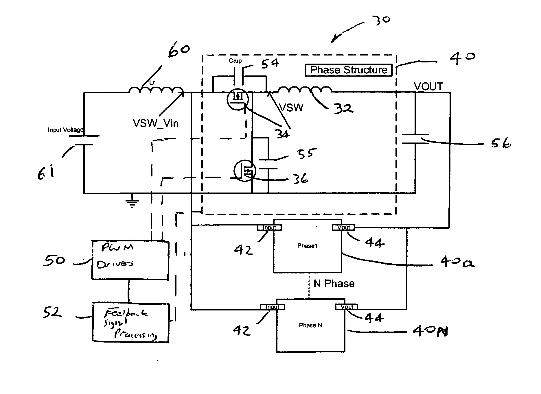
[0039] The present invention improves the overall efficiency of the DC-to-DC converter system because zero voltage switching can be used for non-isolated high input voltage, and low output voltage power converters, for example, “Buck converters.”

[0040] The need for decreasing the size of the converter, along with the need for higher power densities, implies an increase of...


PUM


Abstract

A multiphase DC-to-DC converter includes at least two phase circuits each having upper and lower power switches and a front-end inductor that is operative for forming a resonant tank circuit with the phase circuits to ensure zero voltage switching and minimizing power losses.

Description

RELATED APPLICATION [0001] This application is based upon prior filed copending provisional application Ser. No. 60 / 538,091 filed Jan. 21, 2004.FIELD OF THE INVENTION [0002] The present invention relates to the field of electronic circuits, and more particularly, to DC-to-DC converters and switch mode power supplies for example, Buck converters. BACKGROUND OF THE INVENTION [0003] DC-to-DC converters typically are designed as switching-regulated power supplies also known as a switch-mode power supplies. Some DC-to-DC converters raise voltage from a lower input voltage (a step-up converter), and others lower voltage from a higher input voltage (a step-down converter). One type of step-down switch mode power supply that lowers the voltage is known as a Buck converter, a type of switch mode regulator / or switching power supply. These devices resemble a linear power supply in some respects, but in other ways they are much different. A switching power supply typically includes an energy-st...

Claims


Application Information

Patent Timeline
Patent Type & Authority Applications(United States)
IPC IPC(8): H02M3/158
CPCH02M3/1584Y02B70/1466Y02B70/1425H02M3/1588Y02B70/10
Inventor MOUSSAOUI, ZAKIVICTORIN, THOMAS
Owner INTERSIL INC
Why Eureka
Try Eureka