
High efficiency DC to ac power converter

Inactive Publication Date: 2008-04-17
HSU CHENG CHIA +1
View PDF4 Cites 10 Cited by
  • Summary
  • Abstract
  • Description
  • Claims
  • Application Information

AI Technical Summary

Benefits of technology

[0008] It is, therefore, an object of the present invention to provide a high efficiency DC to AC power converter capable of achieving zero voltage switching by provision of an inductive impedance in a conversion circuit.
[0009] It is another object of the present invention to provide a high efficiency DC to AC power converter capable of enhancing power conversion efficiency.
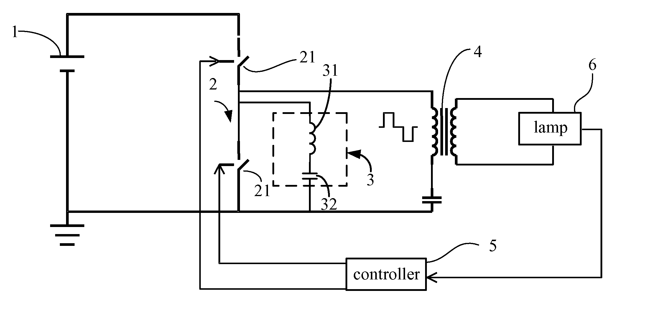
[0010] The high efficiency DC to AC power converter according to the present invention comprises a DC power generator, a filter / rectifier, a transformer, a lamp, a controller and an inductive impedance. The controller is used to activate or deactivate the filter / rectifier. The filter / rectifier is used to acquire and rectify and filter a DC power transmitted from the DC power generator. Then, the inductive impedance is used to convert an overall impedance into being inductive. Finally, the transformer converts the rectified and filtered DC power into an AC power. As such, the purpose of zero voltage switching is achieved and power conversion efficiency of the power converter is enhanced. The inductive impedance takes a form of a single inductance, an inductance and a capacitor connected in series therewith, an inductor, a capacitor and a resistor connected in series therewith, or an inductor, a capacitor and a resistor connected in series and parallel therewith. The filter / rectifier may be a half-wave rectifier or a full-wave rectifier.

Problems solved by technology

According to the related knowledge, the capacitive load may not achieve zero voltage switching in the DC to AC converter and thus switching loss is increased and power conversion efficiency is adversely influenced.

Method used


Image

  • High efficiency DC to ac power converter
  • High efficiency DC to ac power converter
  • High efficiency DC to ac power converter

Examples


Embodiment Construction

[0023] Referring to FIG. 4, a schematic diagram of a first conversion circuit for a high efficiency direct current (DC) to alternating current (AC) power converter according to the present invention is depicted therein. The first conversion circuit comprises a DC power generator 1, a half-wave rectifier 2, an inductive impedance 3, which is an inductor 31 connected in series with a capacitor 32, a transformer 4, a controller 5 and a lamp 6. The half-wave rectifier 2 is composed of two switches 21, which are operatively controlled by the controller 5 so that a DC power may be rectified and filtered. Specifically, a DC power transmitted from the DC power generator 1 is first acquired by the half-wave rectifier 2 and then the acquired DC power is rectified and filtered. Next, the inductive impedance 3 enables an overall impedance to be inductive. Finally, the rectified and filtered DC power is converted into an AC power through the transformer 4, the AC power being used as a power sour...


PUM


Abstract

A high efficiency DC to AC power converter capable of achieving zero voltage switching by provision of an inductive impedance in a conversion circuit. The inductive impedance takes a form of an inductance connected in series with a capacitor. In addition, the inductive impedance may be provided in a half-wave or full-wave conversion circuit for the high efficiency DC to AC power converter.

Description

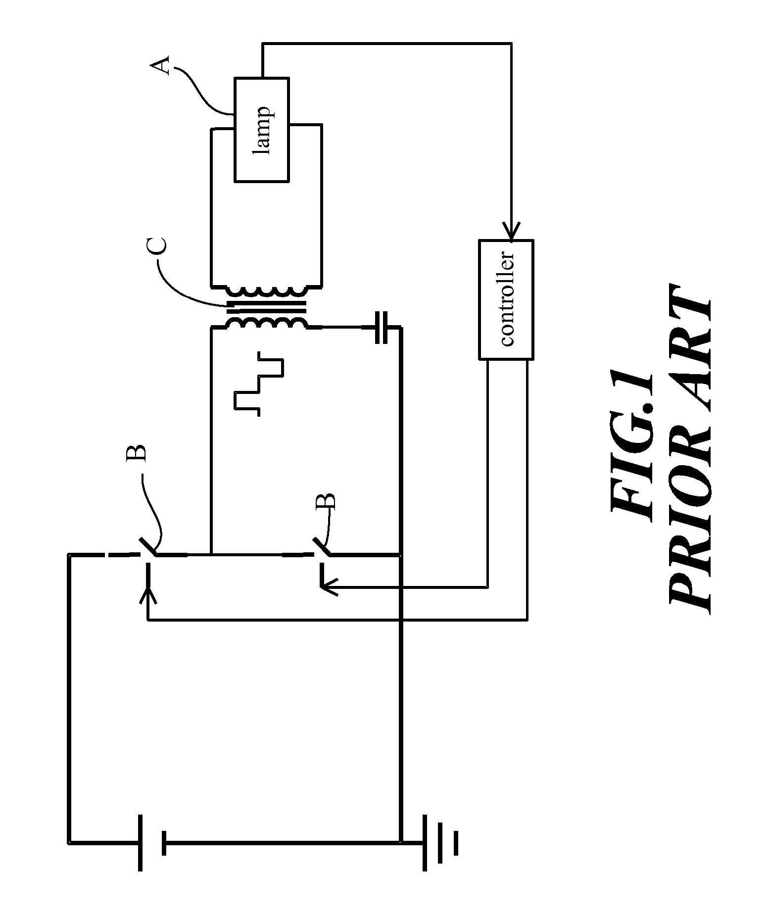
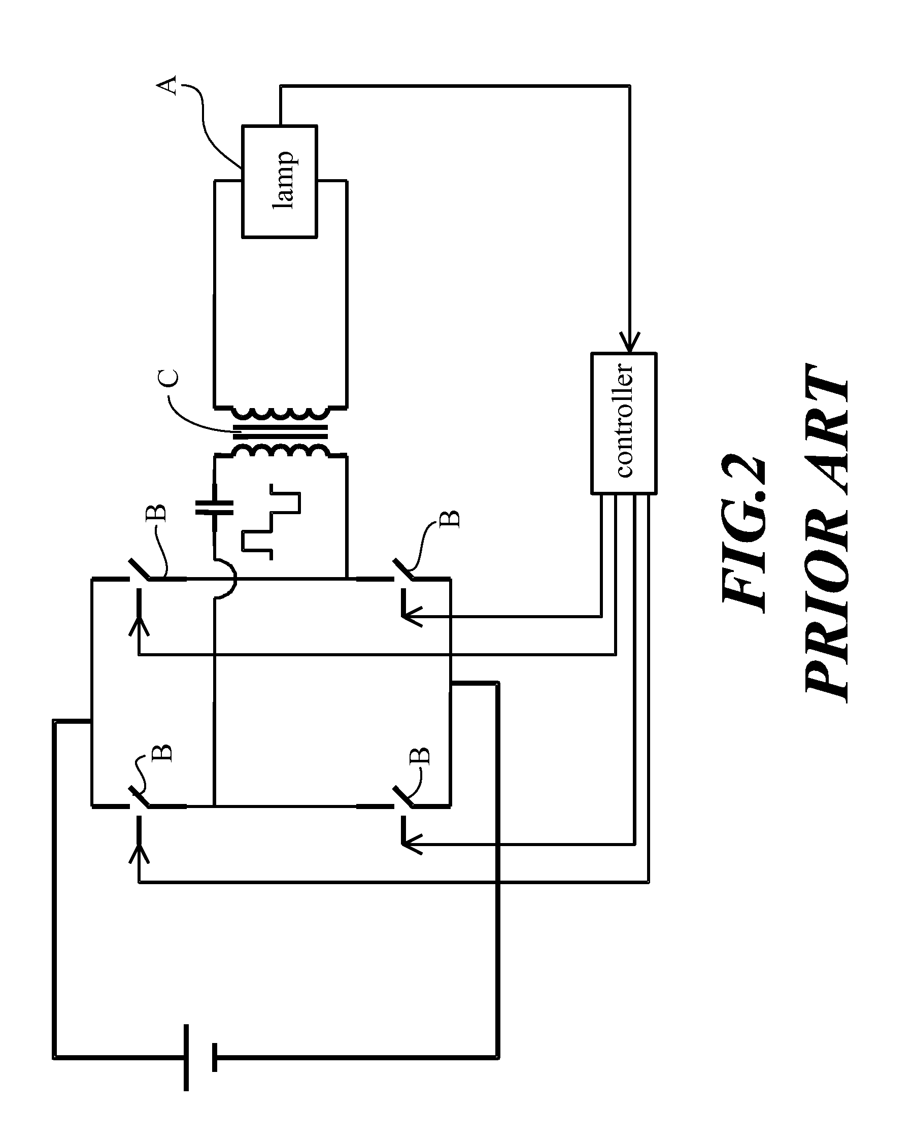
RELATED APPLICATIONS [0001] This application is a continuation-in-part of U.S. patent application Ser. No. 11 / 150,220, filed on Jun. 13, 2005.BACKGROUND OF THE INVENTION [0002] 1. Field of the Invention [0003] The present invention relates to a high efficiency direct current (DC) to alternating current (AC) power converter and particularly to a high efficiency DC to AC power converter capable of achieving zero voltage switching by provision of an inductive impedance in a conversion circuit. [0004] 2. Description of the Prior Art [0005]FIG. 1 and FIG. 2 respectively show a half-wave and a full-wave conversion circuit for a conventional direct current (DC) to alternating current (AC) power converter. For both the half-wave or full-wave conversion circuits, a lamp A therein is capacitive. Power is provided to the load, lamp A, through switch B, it being converted from DC power to AC power. Thus, the converted AC power is also capacitive. According to the related knowledge, the capaciti...

Claims


Application Information

Patent Timeline
IPC IPC(8): H02M7/5387H02M7/537
CPCH02M7/5387H05B41/2856H05B41/2825Y02B70/10H02M7/4815
Inventor HSU, CHENG-CHIAWU, YUN-CHING
Owner HSU CHENG CHIA
Learn More