Image conversion method and apparatus, and pattern identification method and apparatus

Active Publication Date: 2010-12-30
CANON KK
View PDF3 Cites 119 Cited by
  • Summary
  • Abstract
  • Description
  • Claims
  • Application Information

AI Technical Summary

Problems solved by technology

As described above, a conversion method such as LBP may largely change the converted value for a pattern variation such as rotation, and is therefore supposed to be less robust.
In CT, since a converted value corresponding to a pixel of interest is a high-dimensional value, a problem called “curse

Method used


Image

  • Image conversion method and apparatus, and pattern identification method and apparatus
  • Image conversion method and apparatus, and pattern identification method and apparatus
  • Image conversion method and apparatus, and pattern identification method and apparatus

Examples


first embodiment

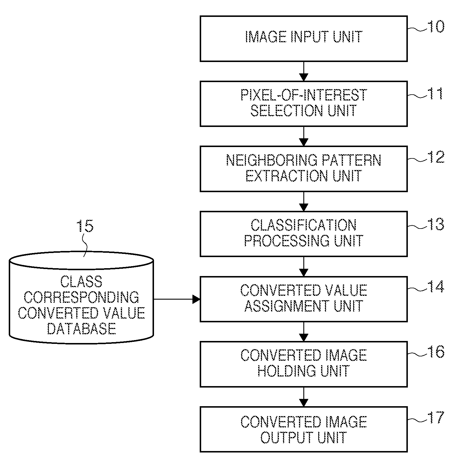
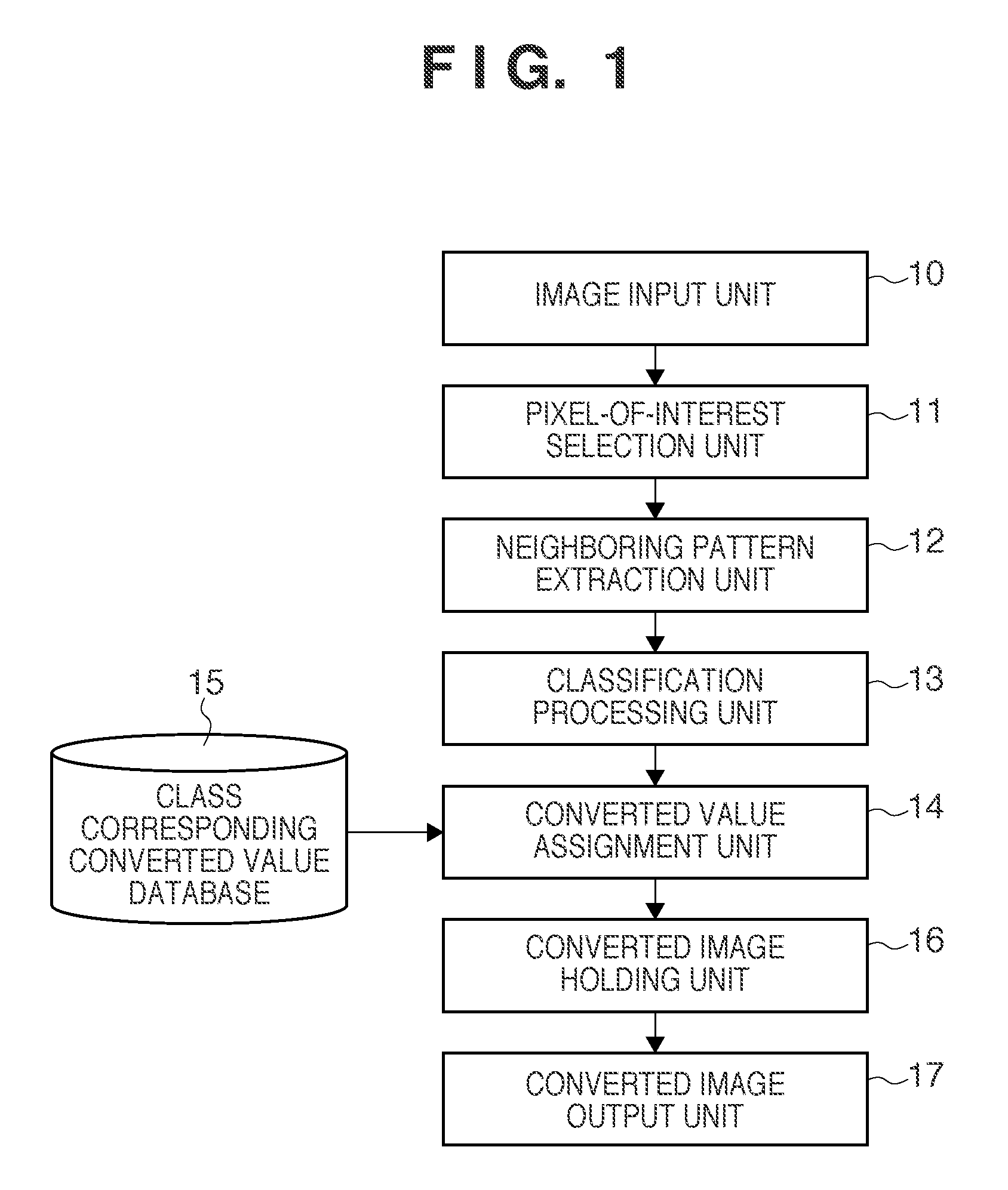
[0066]An outline of the first embodiment will be described first. In an image conversion method according to this embodiment shown in FIGS. 1 and 4, an image input unit 10 sequentially selects a pixel of interest of an input image (steps 40 and 41). A neighboring pattern extraction unit 12 acquires a neighboring pattern based on the values of peripheral pixels at predetermined positions relative to the position of the selected pixel of interest (step 42). As the peripheral pixels, eight pixels at the periphery of a 3×3 pixel pattern with a pixel of interest at the center as shown in FIGS. 3A to 3C are usable.

[0067]Next, a classification processing unit 13 classifies the neighboring pattern as one of a plurality of classes defined in advance (step 43). In the first embodiment, classification is performed based on the pixel value comparison result between the selected pixel of interest and the peripheral pixels. This will be explained later in detail.

[0068]Based on the mutual relation...

second embodiment

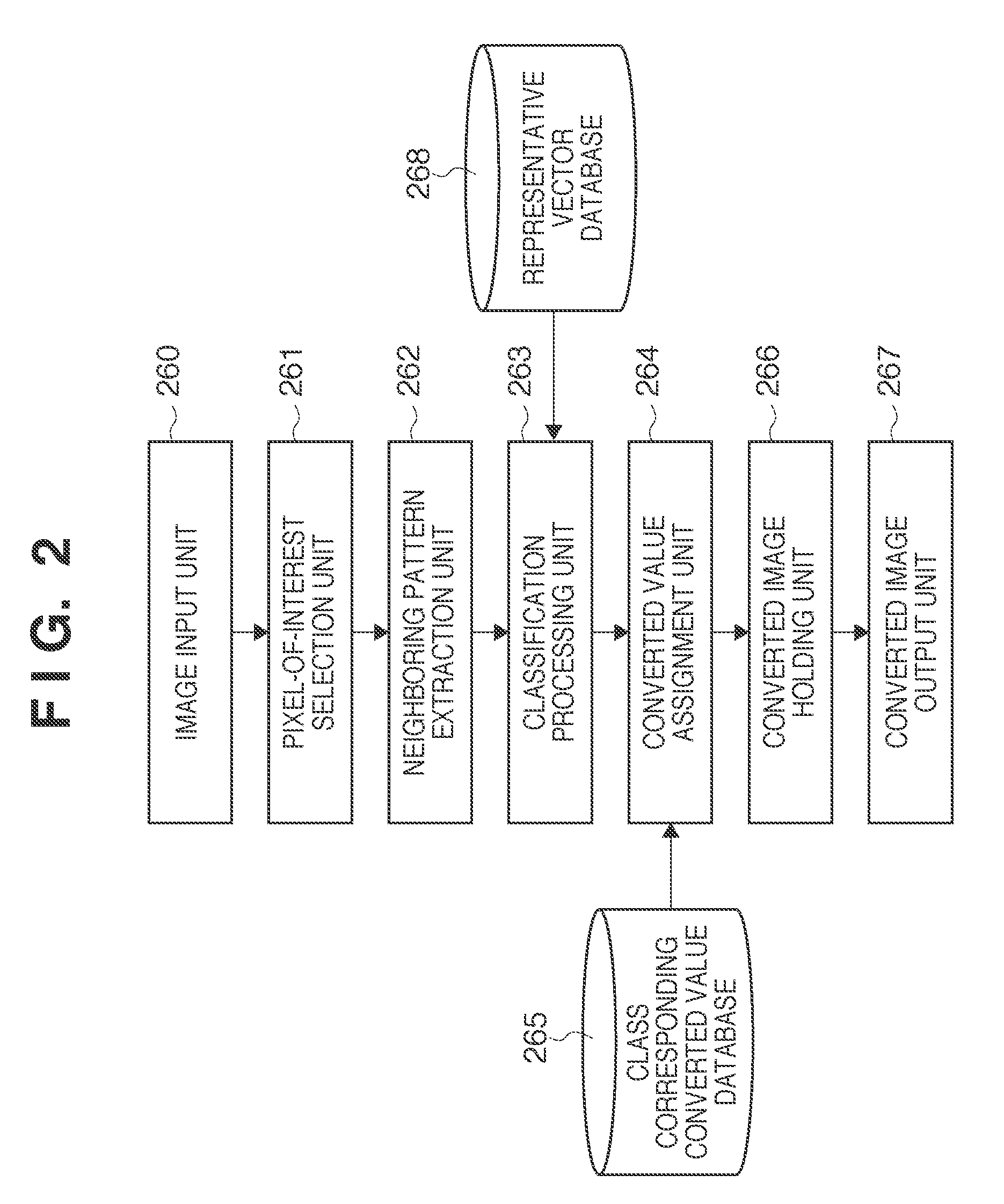
[0110]In the second embodiment, an example will be described in which the method used in the first embodiment to obtain converted values corresponding to classes is modified.

[0111]As the mutual relationship between the plurality of classes, the distance or similarity between representative patterns set for the classes is usable. For example, a numerical value sequence formed from eight {0,1}s based on a value comparison result described above is defined as the representative pattern of each class. The distance or similarity between them can be used. A case in which a numerical value sequence representing a result of value comparison is used will be described below.

[0112]In the first embodiment, numerical values which can preserve the distances between the 3×3 pixel pattern groups serving as the generation sources of the classes as much as possible are used as converted values corresponding to the classes. In the second embodiment, however, instead of performing statistical processin...

third embodiment

[0130]In the third embodiment, an example will be described in which the process contents of the processing units in the first embodiment are modified. An example of a pattern identification method of identifying a converted image as the face image of a specific person will also be described, as in the first embodiment.

[0131]The arrangement of processing units according to this embodiment is the same as in the first embodiment shown in FIG. 1. The processing procedure is also the same as in FIG. 4. However, the process contents of the processing units are slightly different. Parts where the process contents are different from those of the first embodiment will be described with reference to FIGS. 1 and 4, and a description of the remaining parts will not be repeated.

[0132]First, an image input unit 10 inputs a grayscale image corresponding to an extracted human face and including 20×20 pixels, as in the first embodiment (step 40).

[0133]A pixel-of-interest selection unit 11 selects a...


PUM


Abstract

In an image conversion method, a value which reflects the mutual relationship between the classes of pixel patterns each formed from a pixel classified as one of a plurality of classes and peripheral pixels is set as a converted value corresponding to each of the plurality of classes, a pixel of interest is sequentially selected from the input image, and a pixel pattern formed from the selected pixel of interest and a predetermined number of pixels around it is classified as one of the plurality of classes in accordance with a neighboring pattern obtained based on the relationship between the value of the pixel of interest and the values of peripheral pixels located at predetermined relative positions with respect to the pixel of interest. The value of the pixel of interest is converted into a converted value set for a class to which the pixel of interest has been classified.

Description

BACKGROUND OF THE INVENTION[0001]1. Field of the Invention[0002]The present invention relates to an image conversion method and apparatus and a pattern identification method and apparatus which are robust against a variation in the brightness or contrast of an image caused by a difference of illumination environment or the like.[0003]2. Description of the Related Art[0004]As image conversion methods robust against a variation in the brightness or contrast of an image, for example, LBP (Local Binary Pattern) of reference 1 and CT (Census Transform) of reference 2 have received attention. These methods fundamentally convert the value at a position corresponding to a pixel of interest into a sequence of a plurality of numerical values or one scalar value calculated from them based on the result of luminance value comparison between the pixel of interest and each neighboring pixel. Improved methods (reference 3) and pattern identification methods using these conversion methods have also...

Claims


Application Information

Patent Timeline
IPC IPC(8): G06K9/62G06K9/00G06V10/28
CPCG06K9/6251G06K9/38G06V10/28G06V10/54G06V10/7715G06F18/2137
Inventor MITARAI, YUSUKEMATSUGU, MASAKAZUMORI, KATSUHIKO
Owner CANON KK
Why Eureka
Try Eureka