System card architecture for switching device

a switching device and system card technology, applied in the construction details of electrical apparatus, data switching networks, high-level techniques, etc., can solve the problems of imposing a serious overall space problem, increasing system size, cost and complexity, and system in part limited by backplane capacity, so as to reduce the overall signal travel distance, reduce the cost, and the effect of small siz

Active Publication Date: 2011-01-06
TELEFON AB LM ERICSSON (PUBL)
View PDF15 Cites 14 Cited by
  • Summary
  • Abstract
  • Description
  • Claims
  • Application Information

AI Technical Summary

Benefits of technology

[0012]By providing a switching device in which the at least one switch card is arranged perpendicular to the line cards, the switch card can communicate directly with each line card. Thereby, the present need for a backplane conveying signals between the line cards and the switch card(s) in switching devices of today is eliminated.
[0013]The elimination of the backplane in the switching device according to the invention gives many advantages compared to prior-art switching devices for communication networks. The switching device can be made smaller in size and manufactured at a lower cost due to the reduction of required components. The signals between the line cards and the switch card(s) do no longer have to make a detour via a backplane which greatly reduces the overall signal travel distance and allows for high-speed signalling between the line cards and switch card(s) since the limitations previously imposed by backplane capacity are eliminated.
[0014]The switching device may also comprise two switching cards in which case these cards are arranged on two opposite sides of, and substantially perpendicular to, the line cards, thus forming a dual star architecture. This is advantageous if redundant switching cards are needed, which is often required as a system option by network operators.

Problems solved by technology

A problem with electrical backplanes of today arises when high-speed signals, in the order of 10 Gbit / s, need to travel long distances over the backplane or if a large number of high speed signals are needed.
For example, implementing a 100 Gbit / s line card can be done using 10×10 Gbit / s line cards but this imposes a serious overall space problem with current backplane technology.
Together these components impose increased system size, cost and complexity.
With port speeds reaching 40 Gbit / s and eventually 100 Gbit / s, systems are in part limited by the backplane capacity.
To let these systems grow in size is not a satisfactory solution, not only because they occupy more space but since the capacity on the electrical backplane links decrease with increasing signalling distance.
However, optical backplane interconnect equipment of today come at a high cost, in part due to the need for optical connectors.
Thus, optical backplanes have found limited market interest so far.

Method used


Image

  • System card architecture for switching device
  • System card architecture for switching device
  • System card architecture for switching device

Examples


Embodiment Construction

[0030]In the following description, for purposes of explanation and not limitation, specific details are set forth, such as particular network switch components and configurations, in order to provide a thorough understanding of the present invention. However, it will be apparent to one skilled in the art that the present invention may be practiced in other embodiments that depart from these specific details. In other instances, detailed descriptions of well-known network switch components and configurations are omitted so as to not obscure the description of the present invention with unnecessary detail. So for example will the electronic / optoelectronic details as well as the mechanical details of the network switching device according to the invention be much simplified for illustrative purposes.

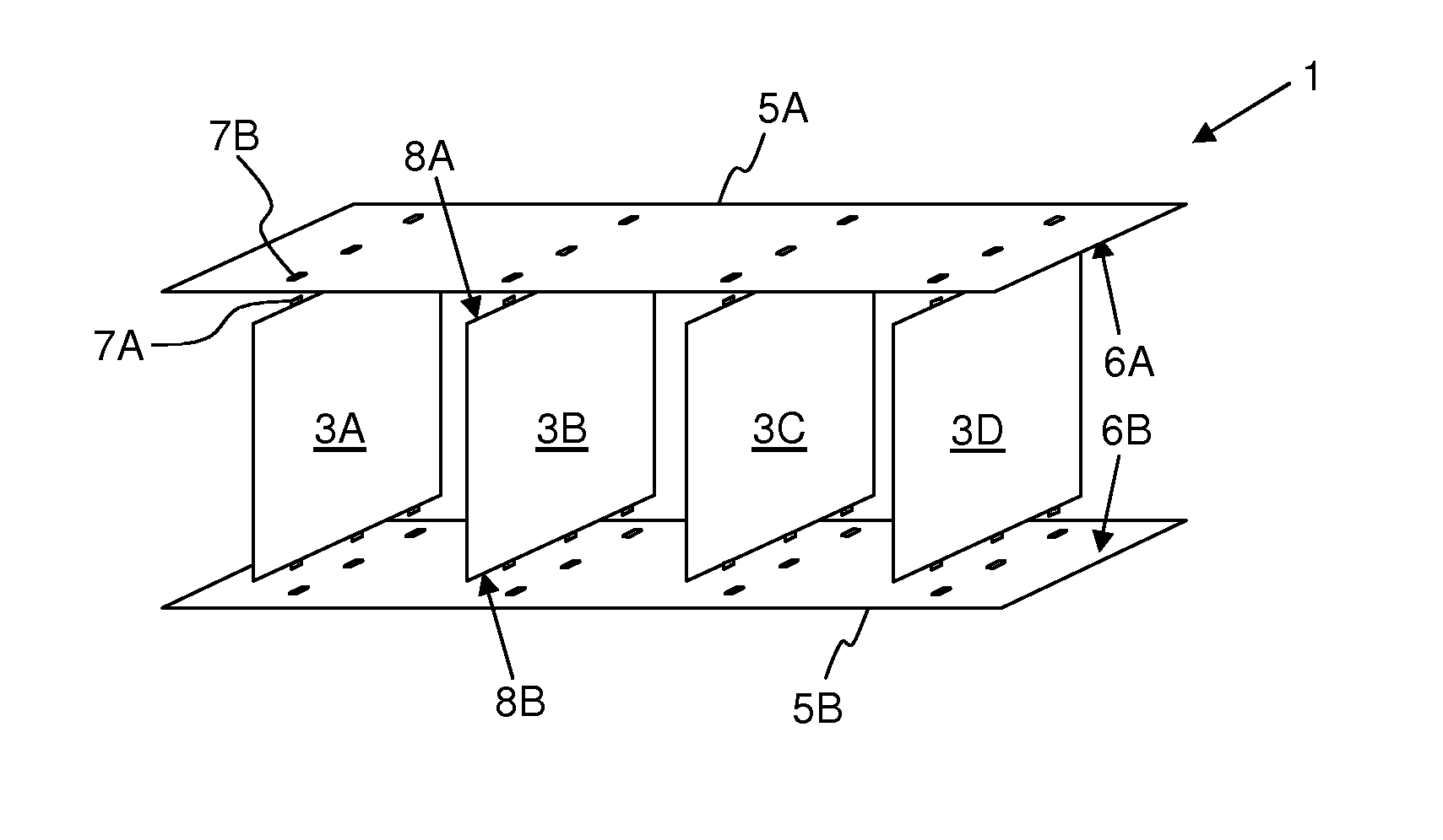
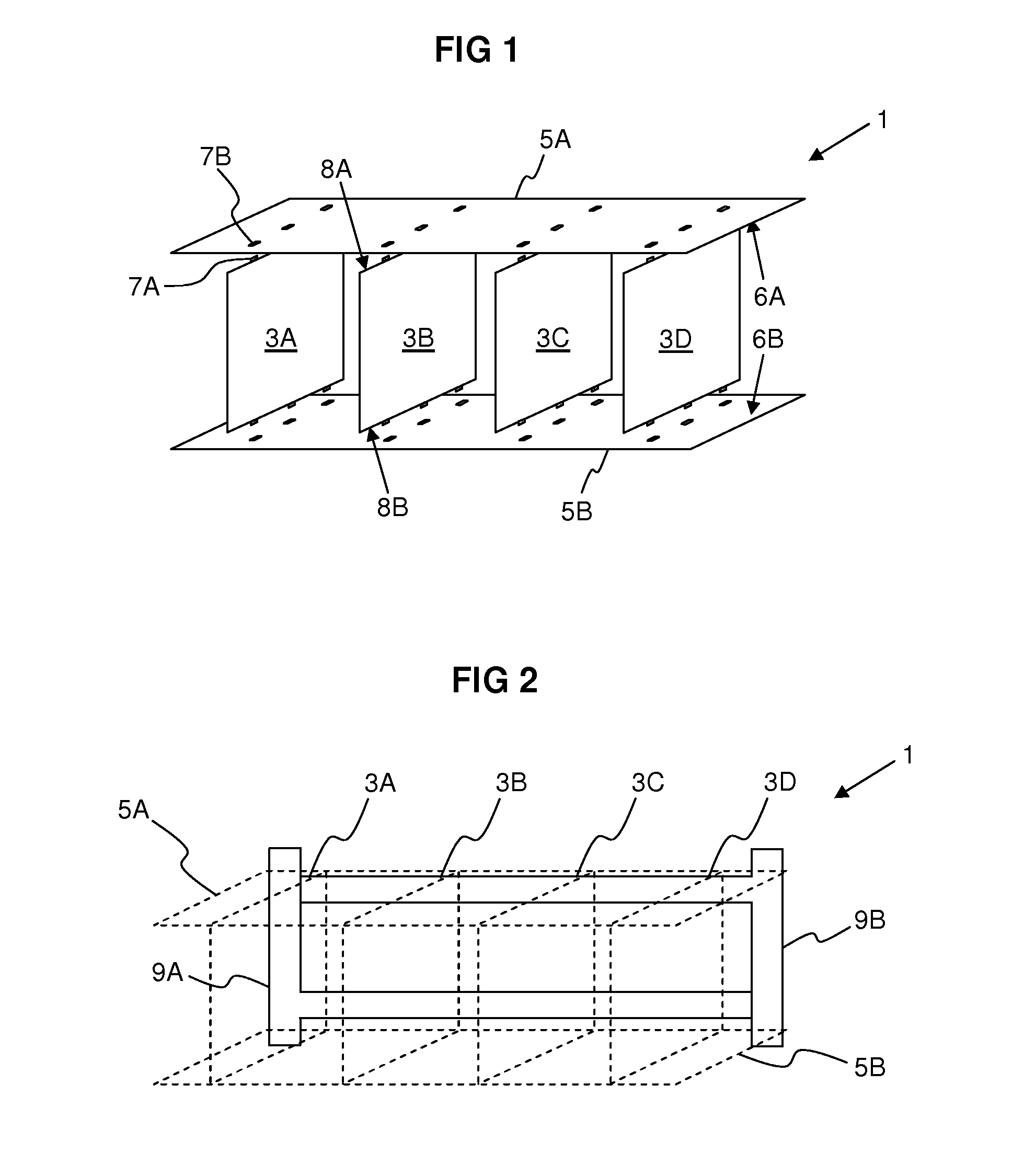
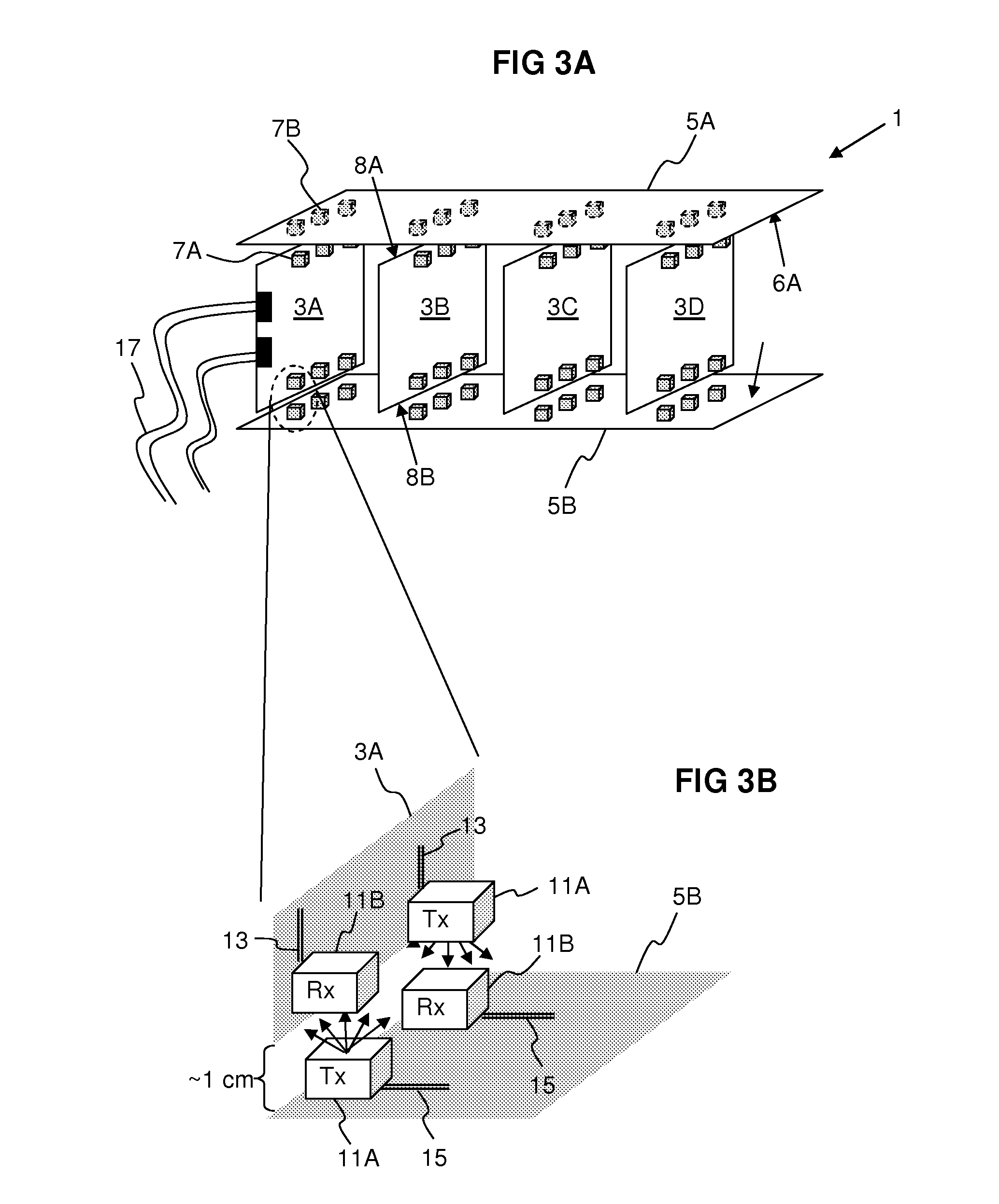
[0031]FIG. 1 schematically illustrates a network switching device 1 according to the invention. A plurality of line cards 3A-D facing each other with their flat sides are aligned in parall...


PUM


Abstract

It is an object of the present invention to provide switching equipment for communications networks, which switching equipment supports high-speed signalling between switch cards and line cards. Hence, the invention relates to a switching device for communications networks comprising a plurality of line cards and at least one switch card. The line cards comprise connection means arranged on or close to one edge of each line card, and the at least one switch card comprises matching connection means arranged on one flat side of said switch card. In this way, when said switch card is arranged substantially perpendicular to said line cards with said flat side of the switch card facing and at least partially overlapping said edges of the line cards, interconnection is achieved between the connection means of the line cards and the matching connection means of the at least one switch card.

Description

TECHNICAL FIELD[0001]The present invention relates to switching equipment in communication networks in general, and in particular to a new type of system card architecture in a network switching device.BACKGROUND[0002]In the fields of telecommunications and data communications, switching equipment is used to connect calls or data sessions between different nodes and / or users. The hardware that performs the switching is in general a modular system of electronic components contained in metal enclosure, sometimes referred to as “shelf”, “rack” or a “chassis”. Typically, a plurality of such shelves is contained in a switch cubicle or frame. A frame that comprises one or several shelves and is connected to a network is sometimes referred to as a switching node, or, in the context of circuit switched networks, a network element.[0003]Normally, each shelf comprises a plurality of line cards and one or two switch cards which are all edgeways inserted in the shelf in parallel with each other...

Claims


Application Information

Patent Timeline
Patent Type & Authority Applications(United States)
IPC IPC(8): H05K7/14H04L49/40
CPCH04L49/40H04Q1/08Y02B60/44H04Q1/15H04Q1/035Y02D30/00
Inventor DAHLFORT, STEFANIN DE BETOU, EINAR
Owner TELEFON AB LM ERICSSON (PUBL)
Why Eureka
Try Eureka