Wireless communication system and wireless communication apparatus

a wireless communication and wireless communication technology, applied in the field of wireless communication system and wireless communication apparatus, can solve the problems of wireless communication system, inability to perform mac for a plurality of channels having different bandwidths, and inability to use the resolving means described abov

Active Publication Date: 2008-09-30
KK TOSHIBA
View PDF12 Cites 9 Cited by
  • Summary
  • Abstract
  • Description
  • Claims
  • Application Information

AI Technical Summary

Benefits of technology

[0014]In view of the foregoing problem, it is an object of the invention to provide a wireless communication system, a wireless communication method and a wireless communication apparatus capable of performing MAC for a plurality of channels having different bandwidths coexisting in the same frequency band in a wireless communication system to make direct communication among wireless terminal stations without passing through a central control station.

Problems solved by technology

In wireless communication, since it is hard for the communication apparatus to monitor transmission data while transmitting the transmission data, MAC without assuming detection of the collision is required.
Conventional CSMA / CA, however, is designed so as to perform access control for a single channel, so that it cannot perform MAC for a plurality of channels having different bandwidths.
Such a wireless communication system in which the central control station does not exist, however, cannot use the resolving means described above.

Method used


Image

  • Wireless communication system and wireless communication apparatus
  • Wireless communication system and wireless communication apparatus
  • Wireless communication system and wireless communication apparatus

Examples


first embodiment

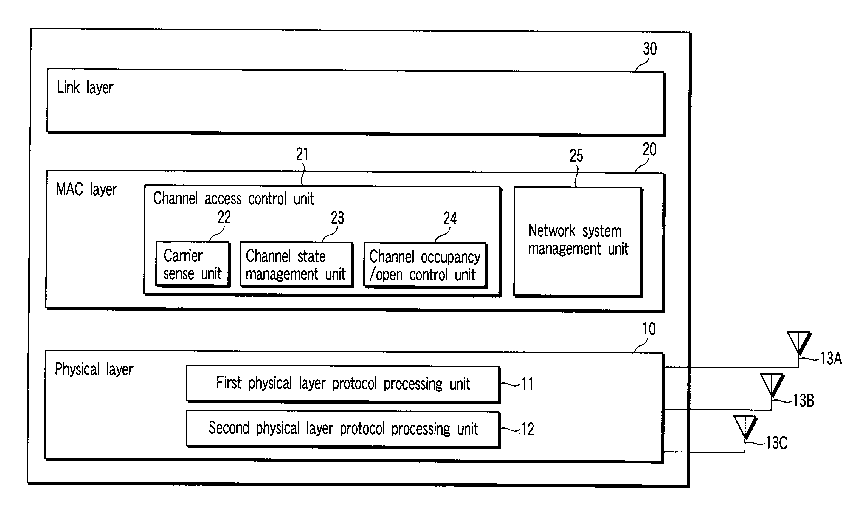
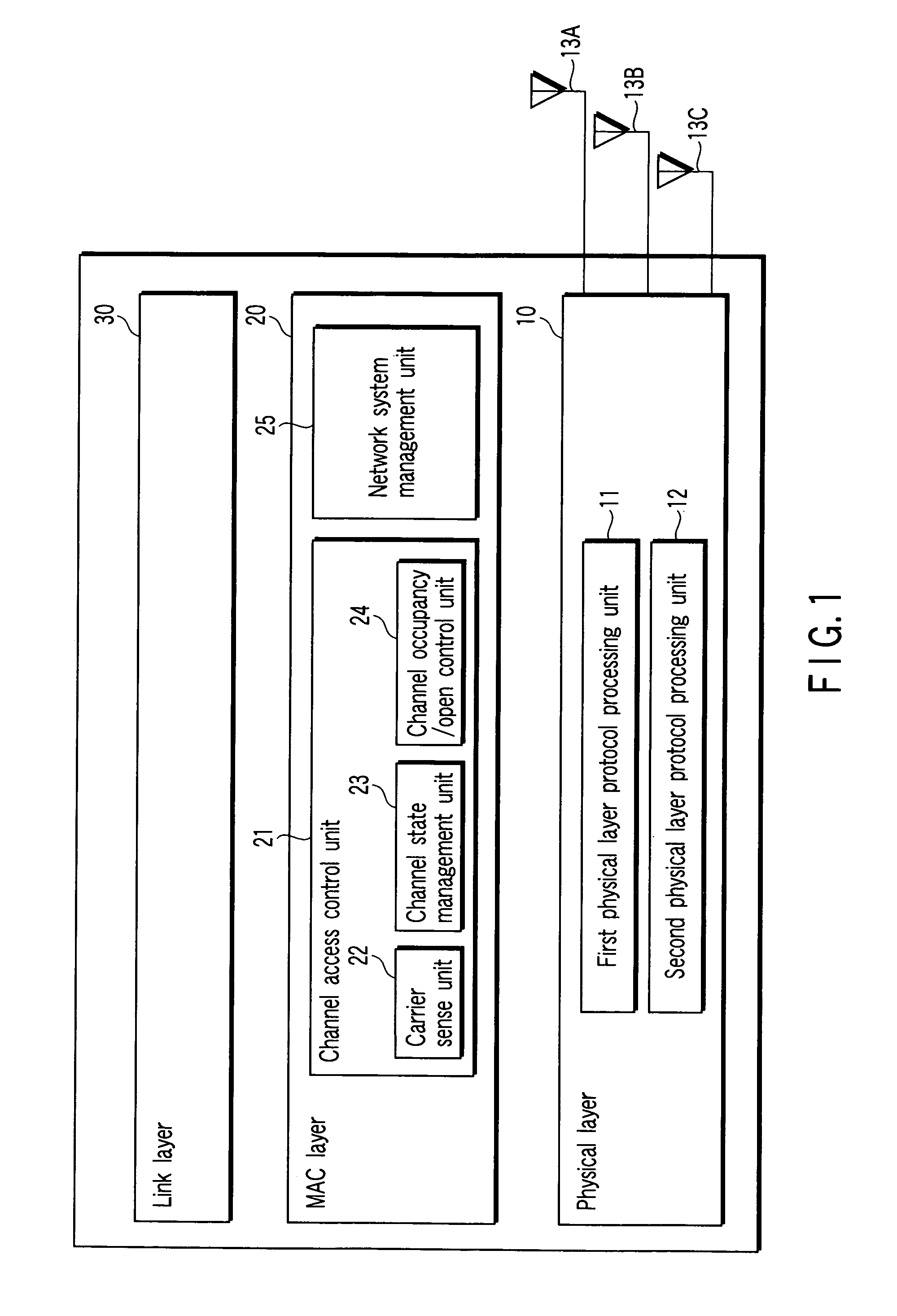
[0032]As shown in FIG. 1, a wireless communication apparatus in accordance with a first embodiment of the invention includes a PHY layer 10, a MAC layer 20 and a link layer 30 by roughly classifying. In FIG. 1, the PHY layer 10 corresponds to two kinds of PHY layer protocols differing in bandwidth in use. That is, the PHY layer 10 has a first PHY layer protocol processing unit 11 for performing PHY layer protocol processing to communicate by using a first channel with a first communication bandwidth and a second PHY layer protocol processing unit 12 for performing PHY processing to communicate by using a second channel having a second communication bandwidth greater than that of the first communication bandwidth and overlapping with the first communication bandwidth. The first processing unit 11 and the second processing unit 12 frequently sharing a circuit with each other in terms of actual mounting and they are not exactly independent with each other.

[0033]The protocol processed i...

second embodiment

[0083]The first embodiment shows the case that the STA which has set up the IBSS becomes the 20- / 40-MHz switching owner, and a second embodiment shows the case that the STA which has successfully transmitted a beacon frame becomes the switching owner.

[0084]The beacon frame in the IBSS is independently and dispersedly transmitted among all STAs composing the IBSS. The STA which has primarily set up the IBSS determines a beacon cycle in the IBSS and the value of the beacon cycle is described in the beacon frame and a probe response frame. The STA entering into the IBSS refers to the beacon cycle set in the beacon frame and the response frame.

[0085]In the IBSS, a timing synchronization function (TSF) timer is reset to zero at every target beacon transmission time (TBTT), and each STA tries to transmit the beacon frame at the timing of the reset in accordance with the following procedures.

[0086]Procedures for selecting the switching owner in the second embodiment will be described with ...

third embodiment

[0099]The first embodiment shows the case that the STA which has set up the IBSS becomes the 20- / 40-MHz switching owner, and the second embodiment shows the case that the STA which has successfully transmitted the beacon frame becomes the switching owner. A third embodiment of the invention is the one in which a STA which desires to perform data transmission through a 40-MHz channel becomes a 20- / 40-MHz switching owner.

[0100]In the IBSS, 20-MHz communication is usually performed, and switching between 20-MHz communication and 40-MHz communication is not necessary. Therefore, in the third embodiment, the switching owner is not specified. In such an IBSS, if an amount of transmission data owned by a certain STA is large and the STA desires to perform high-speed communication through the 40-MHz communication, the STA itself becomes the 20- / 40-MHz switching owner to switch the communication in the IBSS from the 20-MHz communication to the 40-MHz communication.

[0101]At first, each STA ch...


PUM


Abstract

A wireless communication system having wireless terminal stations to perform direct communication without passing through a wireless base station. This system includes a wireless communication device which performs either a first wireless communication using a first channel having a first frequency band or the second wireless communication using a second channel having a second frequency band with a bandwidth greater than that of the first frequency band. This system also includes a generation device which generates a switching control frame to control switching between a communication period by the first wireless communication and a communication period by the second wireless communication, and a communication control device which controls the wireless communication device so as to transmit the switching control frame. A wireless terminal station is selected as a temporal central control station having a switching control right to control switching between the first and second wireless communications.

Description

CROSS-REFERENCE TO RELATED APPLICATIONS[0001]This application is based upon and claims the benefit of priority from prior Japanese Patent Applications No. 2004-187032, filed Jun. 24, 2004, the entire contents of which are incorporated herein by reference.BACKGROUND OF THE INVENTION[0002]1. Field of the Invention[0003]The present invention relates to a wireless communication system and a wireless communication apparatus by which a plurality of wireless communication apparatuses make wireless communication with one another by sharing a plurality of different frequency channels.[0004]2. Description of the Related Art[0005]Media access control (MAC) is control that determines how a plurality of communication apparatuses for communicating by sharing the same medium should utilize the medium and transmit communication data. As a result of performing MAC, even if two or more communication apparatuses simultaneously transmit communication data by utilizing the same medium, occurrences of ev...

Claims


Application Information

Patent Timeline
Patent Type & Authority Patents(United States)
IPC IPC(8): H04Q7/24H04B7/00H04J1/00H04L12/413H04Q7/00H04B7/24H04W4/00H04W72/04H04W74/08H04W76/04H04W84/12H04W84/18H04W88/06
CPCH04W76/043H04W88/06H04W84/18H04W76/23
Inventor UTSUNOMIYA, YORIKOADACHI, TOMOKOTAKAGI, MASAHIRONAKAJIMA, TETSUTANDAI, TOMOYANISHIBAYASHI, YASUYUKI
Owner KK TOSHIBA
Why Eureka
Try Eureka