Wireless video transmitter

Active Publication Date: 2011-01-06
MAXELL HLDG LTD
View PDF32 Cites 7 Cited by
  • Summary
  • Abstract
  • Description
  • Claims
  • Application Information

AI Technical Summary

Benefits of technology

[0011]According to the present invention, the response to control commands can be enhanced while securing transmission regions necessary for communications of the control commands between a

Problems solved by technology

Firstly, within one frame for transmission of video, peripheral device-controlling information coming from every video receiver connected is allowed to be transmitted and, therefore, when control information is transmitted from all the video receivers, the region assigned to each video receiver is reduced, because the transmission

Method used


Image

  • Wireless video transmitter
  • Wireless video transmitter
  • Wireless video transmitter

Examples


embodiment 1

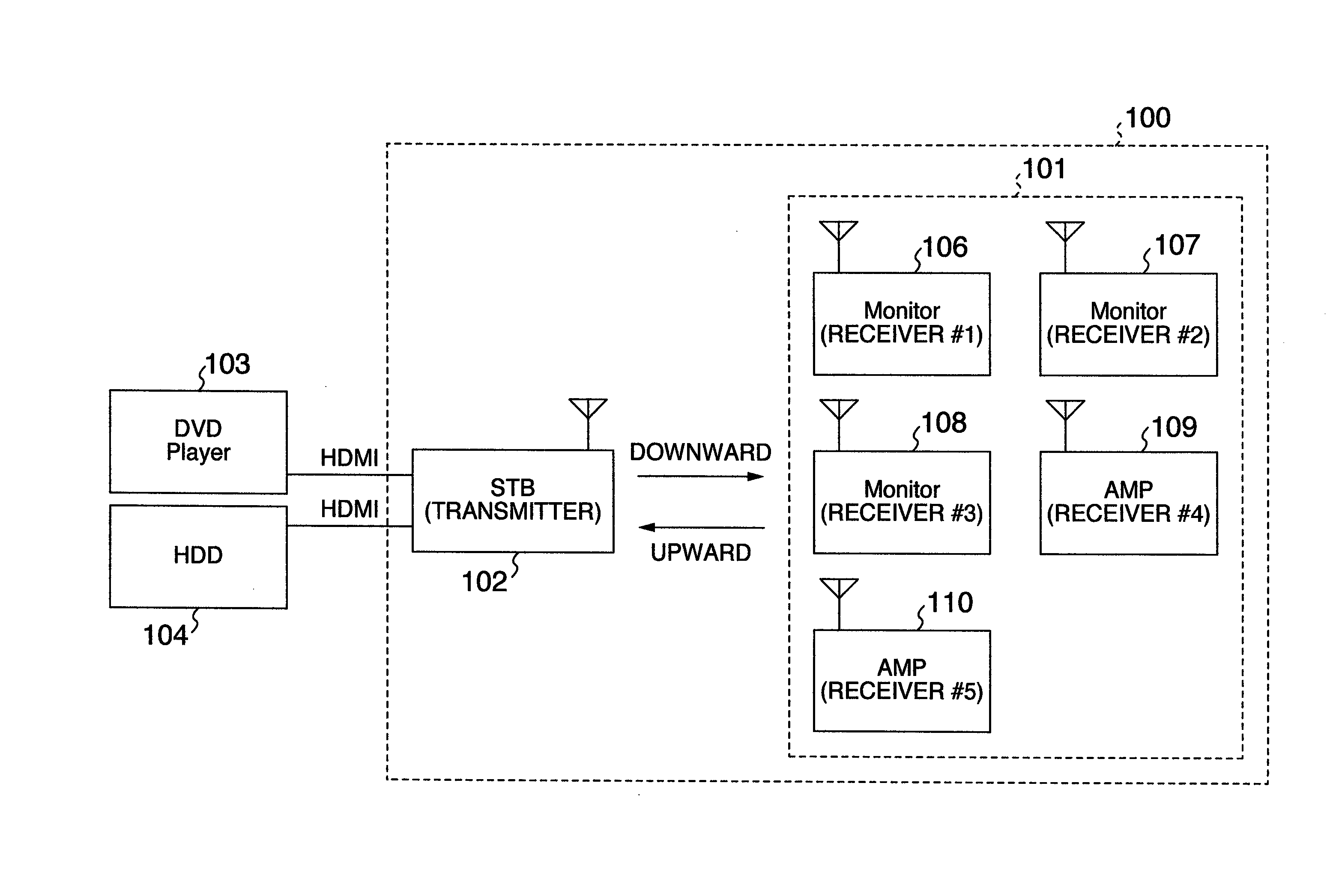
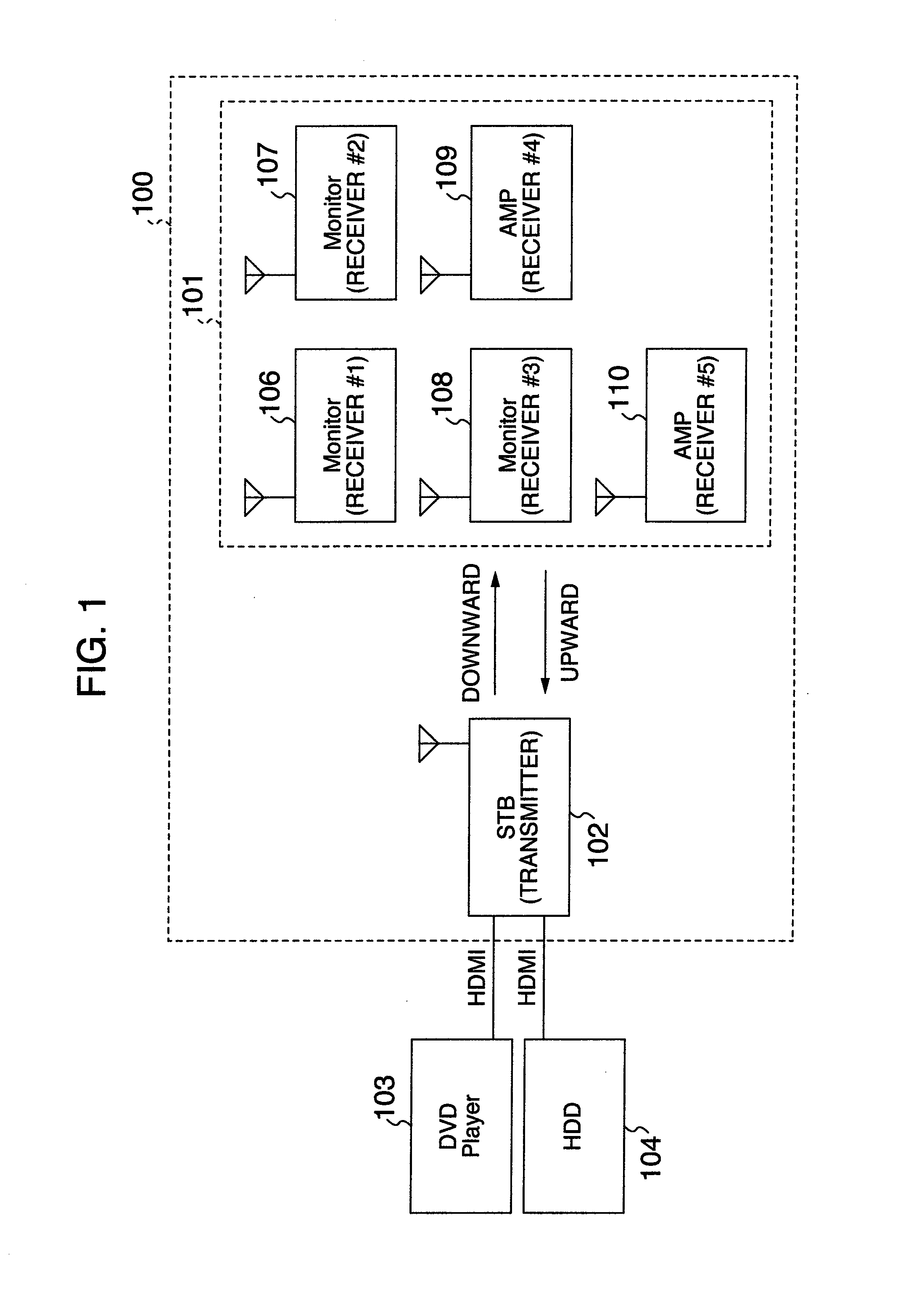
[0027]FIG. 1 is a block diagram showing one example of configuration of a wireless communication system associated with a first embodiment of the present invention. The system has a wireless video transmitter 102, a group of wireless video receivers 101, and a wireless network 100 for wirelessly sending video and audio signals from the wireless video transmitter 102 to wireless video receivers 106-110 (shown as Monitor or AMP) included in the group of video receivers 101 and for communicating control commands between the wireless video transmitter 102 and the wireless video receivers 106-110. The group of video receivers 101 includes the wireless video receivers 106-110 and monitors such as TV sets and amplifiers for outputting of audio. For example, a DVD player 103 for outputting video and audio signals and a HDD recorder 104 are connected with the wireless video transmitter 102 by cables such as HDMI (High-Definition Multimedia Interface) cables. In the following description, the...

embodiment 2

[0062]A second embodiment (Embodiment 2) of the present invention is next described by referring to FIGS. 8 and 9. The second embodiment of the invention is different from the first embodiment in terms of the operation for the wireless video transmitter to assign transmissible periods to the destination of the certain command or to the receiving wireless video receiver in such a way that a higher priority is given to the operation for assignment during reception of control commands than the operation for assignment during transmission of the certain control command.

[0063]FIG. 8 illustrates one example of the configuration of transmissible periods in a case where the second embodiment is applied.

[0064]As already described, when a button is kept pressed for more than 500 ms as shown in FIG. 8, the command in CEC stipulated in the HDMI standard must be resent every 500 ms. That is, in a first case where the wireless video transmitter has received the signal, in a second case where a ...

embodiment 3

[0076]A third embodiment (Embodiment 3) associated with the present invention is next described by referring to FIG. 12. The third embodiment of the invention is different from the first and second embodiments in that plural wireless video receivers are assigned to transmissible periods within one frame.

[0077]FIG. 12 schematically illustrates assignment made when the third embodiment is applied. In the example of FIG. 12, downward and upward transmissible regions are assigned to video signal periods and vertical retrace periods, respectively. Upward control commands are transferred during the vertical retrace periods. Downward control commands are transferred during the video signal periods. Assignment of downward control commands is made by multiplexing data that specify a corresponding wireless video receiver within a video signal sent by the wireless video transmitter.

[0078]Where the wireless transmitter sends contents such as movies, if five wireless video receivers are present ...


PUM


Abstract

A technique is offered which is applied to a system for wirelessly sending and receiving control commands and which permits mutual communications owing to the control commands between a wireless video transmitter and wireless video receivers to be operated stably with low delay. The transmitter makes a decision as to whether commands received from the receivers are certain commands. If so, the transmitter assigns transmissible periods, in which the receivers can send commands, more preferentially to the wireless video receiver that has sent out the certain commands than the other wireless video receivers.

Description

[0001]INCORPORATION BY REFERENCE[0002]The present application claims priority from Japanese Patent Application JP2009-158362 filed on Jul. 3, 2009, the content of which is hereby incorporated by reference into this application.BACKGROUND OF THE INVENTION[0003]The present invention relates to a system for wirelessly sending video and audio signals from a video transmitter to plural video receivers and, more particularly, to a technique for communicating control commands and other commands between the video transmitter and the video receivers.[0004]A technique for sending video signals from a video transmitter to plural video receivers and transmitting control commands between the video transmitter and the video receivers is known, as described in JP-A-11-177965 in which there is disclosed a technique permitting peripheral devices to be controlled at all times by assigning regions for transmitting audio and video and regions for transmitting information for controlling the peripheral ...

Claims


Application Information

Patent Timeline
IPC IPC(8): H04N7/18
CPCH04N5/4403H04N7/088H04N21/4122H04N21/435H04N7/20H04N2005/4407H04N2005/4408H04N7/106H04N21/43637H04N21/42208H04N21/42204H04N21/41265
Inventor OGI, YUYAKABUTO, NOBUAKI
Owner MAXELL HLDG LTD
Why Eureka
Try Eureka