Rotation detection device and bearing having rotation detection device

a detection device and bearing technology, applied in the direction of mechanical equipment, instruments, transportation and packaging, etc., to achieve the effect of reducing the number of processing steps, high precision and high precision

Active Publication Date: 2010-01-28
NTN CORP
View PDF4 Cites 12 Cited by
  • Summary
  • Abstract
  • Description
  • Claims
  • Application Information

AI Technical Summary

Benefits of technology

[0015]In view of the foregoing, the present invention has for its object to provide a rotation detecting system of a type having a high detecting resolution, in which variation in rotational speed to be detected can be minimized to allow detection of the rotational position to be accomplished accurately, in which a sufficient gap can be secured between the sensor and the rotating body and which is effective to simplify assemblage and processing to thereby reduce the manufacturing cost. Another important object of the present invention is to provide the rotation detecting system incorporated bearing assembly, in which the above described rotation detecting system is incorporated.
[0017]Although the multiplied pulses generated by the multiplying section have a pitch error, the pattern of such error has a characteristic repeatability that the pitch error is repeated each time the to-be-detected magnetic pole of the encoder is detected. Accordingly, when the use is made of the speed detecting section to detect the speed, which will become an average speed for the N pieces of the multiplied pulses, at the interval of the pulse before it is multiplied, variations resulting from the pitch error can be averaged and any error in detection speed can be minimized. In this way, since the multiplied pulses are generated from the multiplying section and, with respect to the speed, the speed is outputted at the interval of pulses before the latter are multiplied, it is possible to provide a speed output with good precision, in which the pitch error has been averaged with multiplied high resolution. Also, since the detection speed is detected with the use of all of the multiplied pulses, the detecting rate of the speed increases. In other words, the number of sampling times for detecting the speed can be increased. In this way, the response to control can be increased and even a slight change in speed can be detected with high precision.
[0019]The magnetic encoder has a difficulty in increasing the resolution as compared with an optical encoder, but it has a merit in that it is well adapted to the environment such as, for example, muddy water and / or dusts. For this reason, when the magnetic encoder is used, advantages in that the detecting resolution is high and in that the variation in rotational speed detected is less considerable can be effectively demonstrated and, therefore, the rotation detecting system highly resistant to the environment and having the high resolution can be obtained.
[0022]By so constructing, the speed detecting section which detects the speed with the use of all of the multiplied pulses can be realized with a simplified construction.
[0024]According to this structural feature, by outputting both of the rotational pulses and the speed signals, the processing circuit employed in any machine utilizing the rotation detecting system can be dispensed with or simplified and downsized.
[0028]According to this another aspect of the present invention, not only can the rotation pulse of a high resolution be outputted, but also speed detection with high precision is possible and the number of component parts of the machine utilizing the bearing assembly and the number of processing steps can be reduced, allowing it to be manufactured compact in size.

Problems solved by technology

Although the multiplied pulses generated by the multiplying section have a pitch error, the pattern of such error has a characteristic repeatability that the pitch error is repeated each time the to-be-detected magnetic pole of the encoder is detected.

Method used


Image

  • Rotation detection device and bearing having rotation detection device
  • Rotation detection device and bearing having rotation detection device
  • Rotation detection device and bearing having rotation detection device

Examples


first embodiment

[0089]As hereinbefore described, in the rotation detecting system 1 the speed detection is carried out by utilizing all of the multiplied pulses Pb, which are the pulses Pa generated from the sensor 3 and multiplied. Accordingly, the rate of speed detection, that is, the number of sampling times in speed detection can be increased as shown by x in FIG. 10, to thereby enhance the response to control in the rotation control utilizing the detected speed v. Also, even slight change in speed can be detected with high precision. It is to be noted that blackened triangles employed in FIG. 10 represent the case in which no multiplied pulse Pb is used, that is, a change in speed v detected as a result of the speed detection which has been carried out by the utilization of only the pulses Pa generated from the sensor 3.

[0090]FIGS. 11 and 12 illustrate charts showing a change in pitch error of the detection signal resulting from a change in gap between the sensor and the encoder magnet. In pa...

second embodiment

[0101]The wheel support bearing assembly according to the present invention will now be described in detail.

[0102]In the description that follows, component parts referred to in the following description, but similar to those described in connection with the foregoing embodiment are designated by like reference numerals and, therefore, the details thereof may not be reiterated for the sake of brevity. Also, where only a part of the construction is described in the following description, the remaining part or parts of the construction are to be understood as similar to those described in connection with the foregoing embodiment and that, unless inconveniences may arise in not only a combination of parts which are described in details in the foregoing embodiment, but also a combination in particular, parts of one embodiment can be combined with part of another embodiment.

[0103]The second embodiment specifically shown in FIGS. 13 and 14 is substantially similar to the first embodiment ...

seventh embodiment

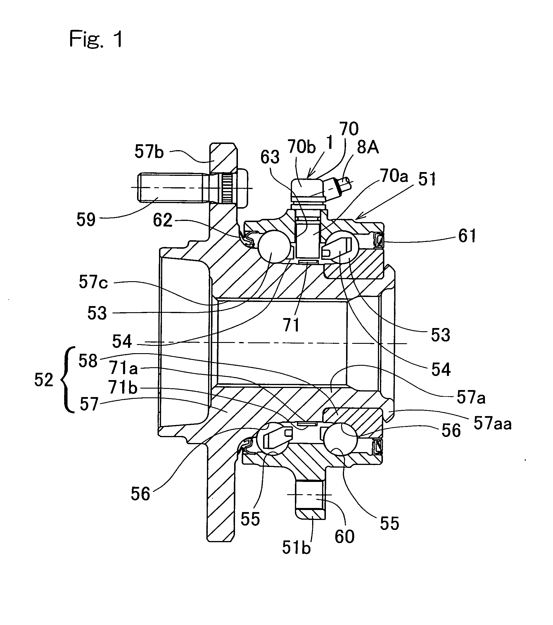
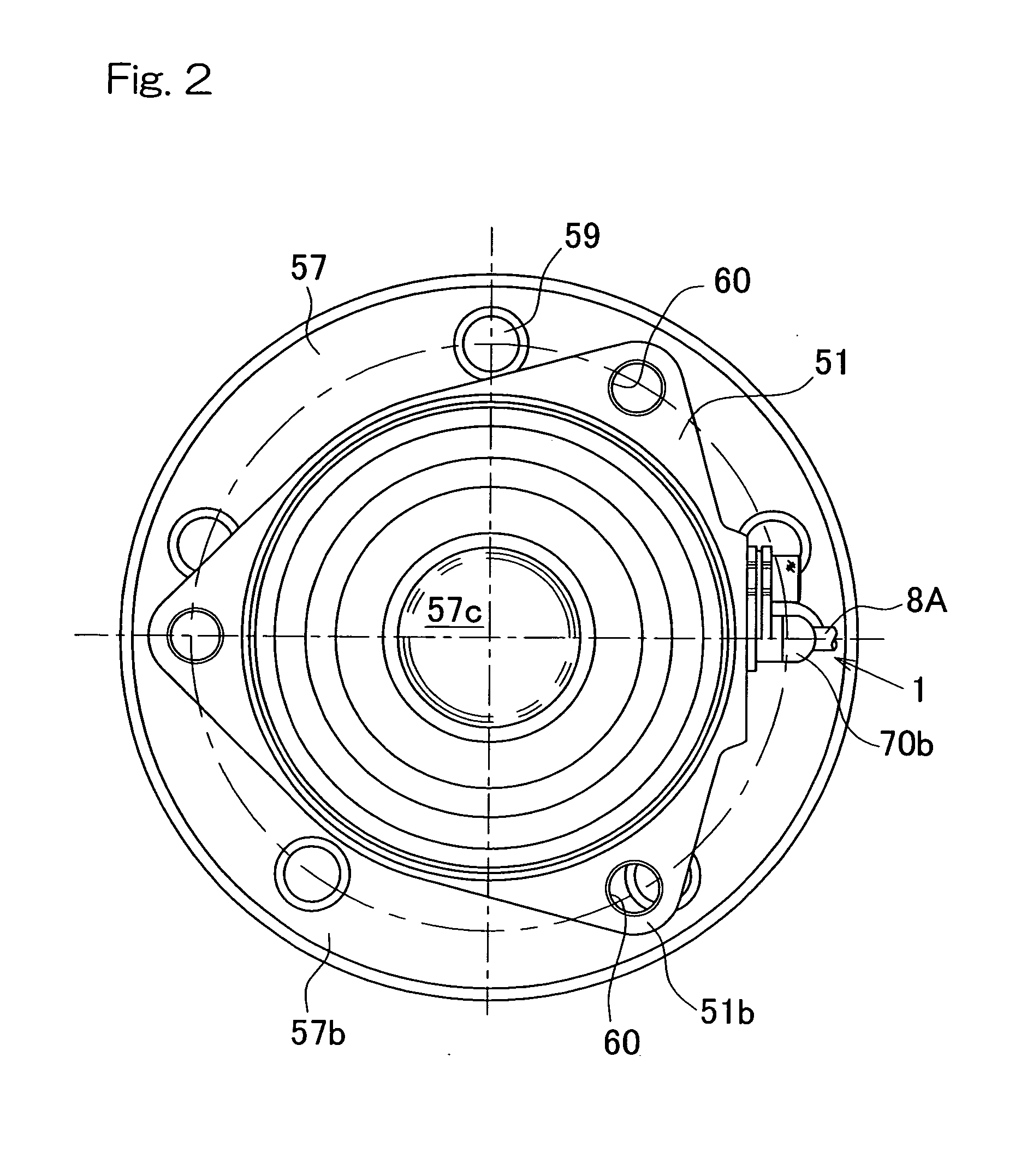
[0111]A seventh embodiment, which is shown in and will now be described with particular reference to FIG. 23, is an embodiment directed to a so-called fourth generation type and, therefore, the inner member 52 is made up of a wheel hub 57A and a constant velocity joint outer race 81.

[0112]A constant velocity joint 80 is of a structure in which a plurality of axially extending raceway grooves are formed on a spherical inner surface of the outer race 81 and a spherical outer surface of an inner race 82, respectively, and torque transmitting balls 83, retained by a ball retainer 84, are interposed between the raceway grooves that are opposed to each other. The constant velocity joint outer race 81 has a cup portion 81a and a hollow stem portion 81b protruding axially from an outer bottom surface of the cup portion 81a. The stem portion 81b is inserted into the wheel hub 57A of the wheel support bearing assembly and is relatively nonrotatably coupled with the wheel hub 57A by means of a...


PUM


Abstract

To provide a rotation detecting system of a type having a high detecting resolution, in which the rotational position can be detected accurately, in which a sufficient gap can be secured between the sensor and the rotating body and which is effective to simplify assemblage and processing to thereby reduce the manufacturing cost, the rotation detecting system is provided with a multiplying section 4 for multiplying the pulses, generated by the sensor 3, by a multiplication factor to form multiplied pulses Pb and a speed detecting section 5 for detecting an period average speed of the encoder 71 during the interval, in which the latest N pieces of the multiplied pulses Pb have been generated where N represents the multiplication factors by which the multiplied pulses Pb have been multiplied.

Description

CROSS REFERENCE TO THE RELATED APPLICATION[0001]This application is a continuation application, under 35 U.S.C. §111(a), of international application No. PCT / JP2008 / 000628, filed Mar. 18, 2008, which claims priority to Japanese patent application No. 2007-087695, filed Mar. 29, 2007 and Japanese patent application No. 2007-218014, filed Aug. 24, 2007, the disclosures of which are incorporated by reference in their entirety into this application.BACKGROUND OF THE INVENTION[0002]1. Field of the Invention[0003]The present invention relates to a rotation detecting system for use in detecting the rotation and / or the rotational speed exhibited by various machines and also to a bearing assembly equipped with such rotation detecting system.[0004]2. Description of the Related Art[0005]The rotation detecting system of this kind is well known, in which a ring shaped encoder having a plurality of circumferentially arranged magnetic pole pairs (N and S), which serve as, for example, to-be-detect...

Claims


Application Information

Patent Timeline
Patent Type & Authority Applications(United States)
IPC IPC(8): G01B7/30
CPCB60B27/0005B60B27/001B60B27/0042B60B27/0068F16C2326/02B60B27/0094G01P3/446G01P3/489F16C41/007B60B27/0084
Inventor UENO, SHINTAROUTAKAHASHI, TORU
Owner NTN CORP
Why Eureka
Try Eureka