Underwater sound array device based on underwater movement platform

A mobile platform and array technology, applied in seismology, measurement devices, instruments, etc. in areas covered by water, can solve problems such as low work efficiency, improve work efficiency, improve resolution, and avoid large attenuation Effect

Pending Publication Date: 2018-05-15
NAT DEEP SEA CENT +1
View PDF0 Cites 16 Cited by
  • Summary
  • Abstract
  • Description
  • Claims
  • Application Information

AI Technical Summary

Problems solved by technology

This conventional underwater acoustic survey method needs to deploy and recover submerged buoys in different locations multiple times, and the work efficiency is low.

Method used


Image

  • Underwater sound array device based on underwater movement platform
  • Underwater sound array device based on underwater movement platform
  • Underwater sound array device based on underwater movement platform

Examples


Embodiment 1

[0069] The specific working steps are as follows:

[0070] (1) The survey ship arrives at the designated working sea area.

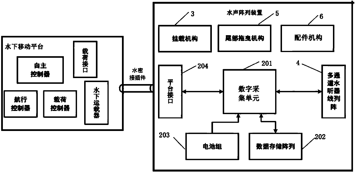
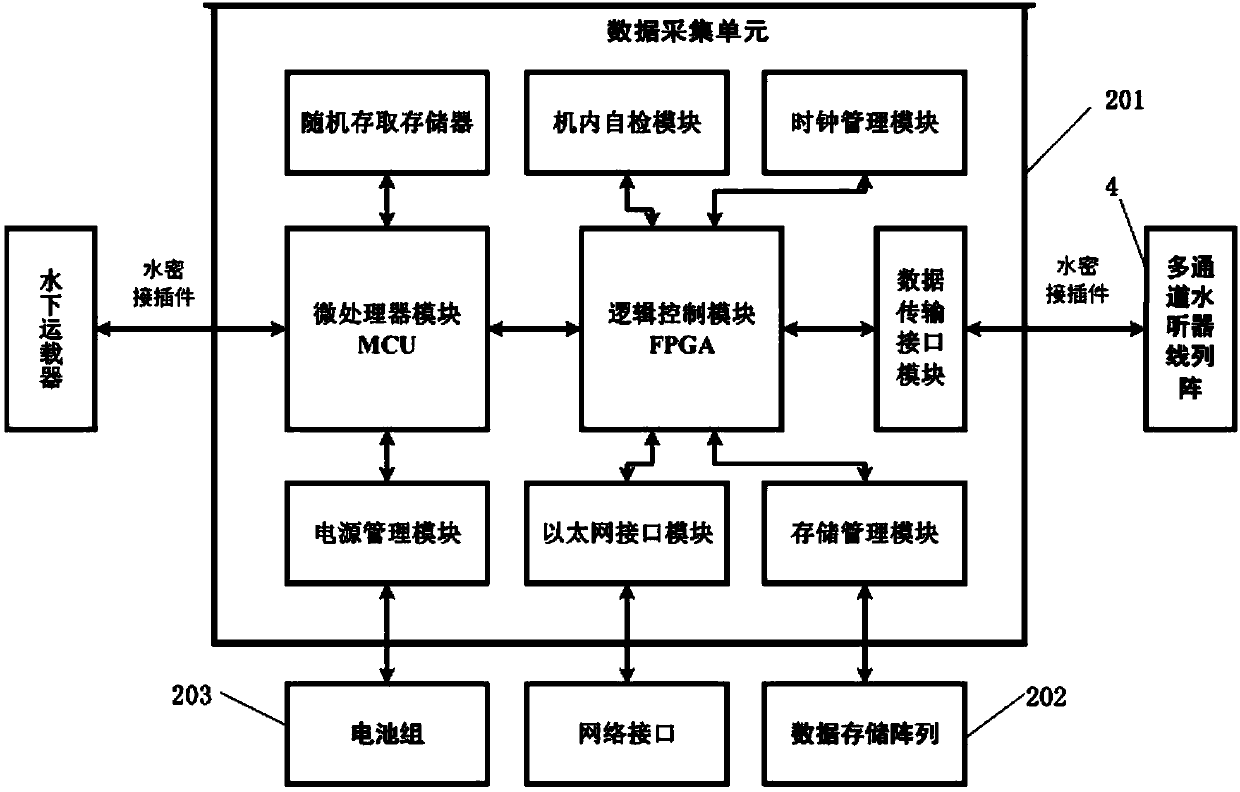
[0071] (2) The user sets the data acquisition unit 201 through the network interface (wired or wireless), sets the working parameters such as sampling interval, sampling rate, and sampling length, and sets the data acquisition unit 201 to work in the automatic working mode, and the test equipment is in normal working condition.

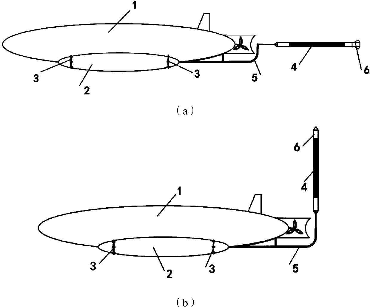
[0072](3) Mount the external self-contained collection cabin on the autonomous underwater vehicle (AUV) through the mounting mechanism 3 .

[0073] (4) The multi-channel hydrophone line array 4 is installed at the tail of the AUV through the tail dragging mechanism 5, and is connected with the external self-contained acquisition cabin. Add a drag parachute to the tail of the multi-channel hydrophone line array 4.

[0074] (5) Set the AUV working parameters, deploy the AUV to the sea surface, and the AUV will sail according to ...

Embodiment 2

[0084] The specific working steps are as follows:

[0085] (1) The survey ship arrives at the designated working sea area.

[0086] (2) The user sets the data acquisition unit 201 through the network interface (wired or wireless), sets the working parameters such as sampling interval, sampling rate, and sampling length, and sets the data acquisition unit 201 to work in the automatic working mode, and the test equipment is in normal working condition.

[0087] (3) Mount the external self-contained collection cabin on the autonomous underwater vehicle (AUV) through the mounting mechanism 3 .

[0088] (4) The multi-channel hydrophone line array 4 is installed at the tail of the AUV through the tail dragging mechanism 5, and is connected with the external self-contained acquisition cabin.

[0089] (5) Set the AUV working parameters, deploy the AUV to the sea surface, the AUV will sail according to the established working parameters, and reach the designated location on the seabed...


PUM


Abstract

The invention discloses an underwater sound array device based on an underwater movement platform. The underwater sound array device is connected with the underwater movement platform and comprises anexternally-mounted self-contained collection bin, a multi-channel hydrophone linear array and a mounting mechanism, wherein the externally-mounted self-contained collection bin is externally mountedand fixed on the underwater movement platform through the mounting mechanism; and the externally-mounted self-contained collection bin is connected with the underwater movement platform and is furtherconnected with the multi-channel hydrophone linear array. By utilizing the underwater sound array device, when seismic exploration work is carried out in a deep sea area, the sharp attenuation of sound waves caused by great-depth sea water is avoided, the seismic exploration resolution ratio is increased, and the stratum penetration depth is increased. When the underwater sound array device is applied to hydroacoustic investigation, the underwater movement platform can be conveniently controlled to be sailed and moved to a seabed on the other position and is static again, so that the time forrecycling and rearranging an underwater sound array is saved, and the working efficiency is improved.

Description

technical field [0001] The invention relates to the technical fields of geophysical exploration and underwater acoustic survey, in particular to an underwater acoustic array device based on an underwater mobile platform. Background technique [0002] Conventional marine seismic exploration usually drags the towed array of hydrophones on the sea surface, receives the seismic waves reflected by the seabed, and further analyzes and judges the geological conditions of the seabed by calculating and drawing the acquired data. When this conventional seismic detection method works in deep-sea areas, due to the substantial attenuation of seawater to sound waves (especially high-frequency sound waves), the detection resolution and penetration depth of conventional seismic equipment for deep-sea formations are reduced. [0003] Conventional underwater acoustic surveys usually deploy one or more hydrophone arrays on the seabed by means of submerged buoys, receive acoustic signals scatte...

Claims


Application Information

Patent Timeline
Patent Type & Authority Applications(China)
IPC IPC(8): G01V1/38
CPCG01V1/3835G01V1/3852
Inventor 刘保华裴彦良阚光明于凯本宗乐孙蕾吕彬连艳红陈自力
Owner NAT DEEP SEA CENT
Why Eureka
Try Eureka