Wireless video transmitter

a video transmitter and wireless technology, applied in the field of wireless video transmitters, can solve the problem that the necessary information cannot be transmitted, and achieve the effect of enhancing the response to control commands and operating stably

Active Publication Date: 2014-05-20
MAXELL HLDG LTD
View PDF39 Cites 0 Cited by
  • Summary
  • Abstract
  • Description
  • Claims
  • Application Information

AI Technical Summary

Benefits of technology

[0006]In view of the foregoing problem, the present invention has been made. It is an object of the invention to provide a technique which is applied to a system for wirelessly sending video and audio signals from a video transmitter to plural video receivers and which can enhance the responsiveness to control commands while securing a transmission region necessary for communications of the control commands between the video transmitter and the video receivers.
[0010]According to the present invention, the response to control commands can be enhanced while securing transmission regions necessary for communications of the control commands between a video transmitter and plural video receivers. Furthermore, mutual communications owing to the control commands between the video transmitter and the video receivers can be operated stably.

Problems solved by technology

Firstly, within one frame for transmission of video, peripheral device-controlling information coming from every video receiver connected is allowed to be transmitted and, therefore, when control information is transmitted from all the video receivers, the region assigned to each video receiver is reduced, because the transmission region is finite, thus creating the possibility that the necessary information cannot be transmitted.
Secondly, the priorities of control information from all the video receivers are not set and so control information with high real-timeness for which settings are established by mutual communications is not processed preferentially.

Method used


Image

  • Wireless video transmitter
  • Wireless video transmitter
  • Wireless video transmitter

Examples


first embodiment

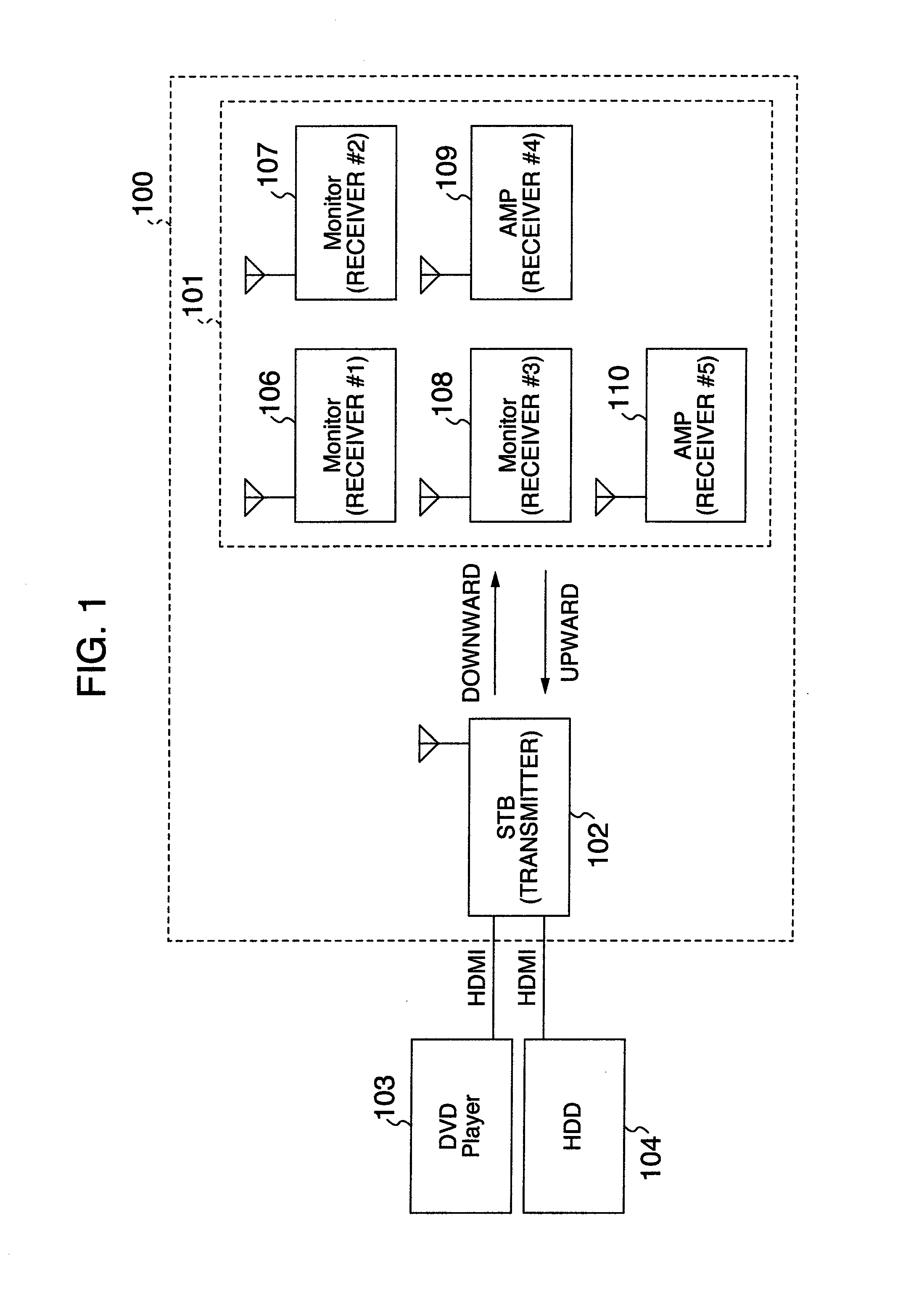
[0026]FIG. 1 is a block diagram showing one example of configuration of a wireless communication system associated with the present invention. The system has a wireless video transmitter 102, a group of wireless video receivers 101, and a wireless network 100 for wirelessly sending video and audio signals from the wireless video transmitter 102 to wireless video receivers 106-110 (shown as Monitor or AMP) included in the group of video receivers 101 and for communicating control commands between the wireless video transmitter 102 and the wireless video receivers 106-110. The group of video receivers 101 includes the wireless video receivers 106-110 and monitors such as TV sets and amplifiers for outputting of audio. For example, a DVD player 103 for outputting video and audio signals and a HDD recorder 104 are connected with the wireless video transmitter 102 by cables such as HDMI (High-Definition Multimedia Interface) cables. In the following description, the DVD player 103, HDD r...

second embodiment

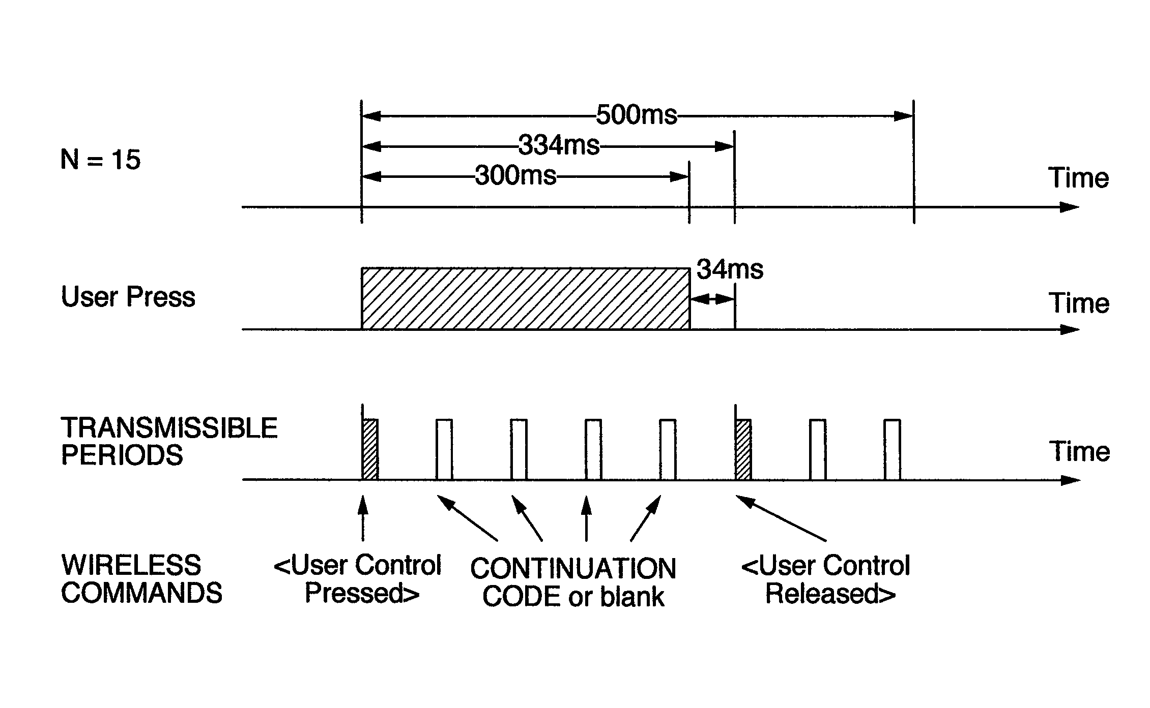
[0062]FIG. 8 illustrates one example of the configuration of transmissible periods in a case where the second embodiment is applied.

[0063]As already described, when a button is kept pressed for more than 500 ms as shown in FIG. 8, the command in CEC stipulated in the HDMI standard must be resent every 500 ms. That is, in a first case where the wireless video transmitter has received the signal, in a second case where a continuation code is received after the end of the reception, or in a third case where a period of 500 ms is likely to elapse since the reception of the command, it follows that a control command will be again received from the device that sent out the command. It is possible to reduce the time lag in the mutual communications between the wireless video transmitter and the wireless video receiver by assigning the wireless video receiver sending out the command to periods in which transmission and arrival of commands are highly likely to occur.

[0064]A routine (proce...

third embodiment

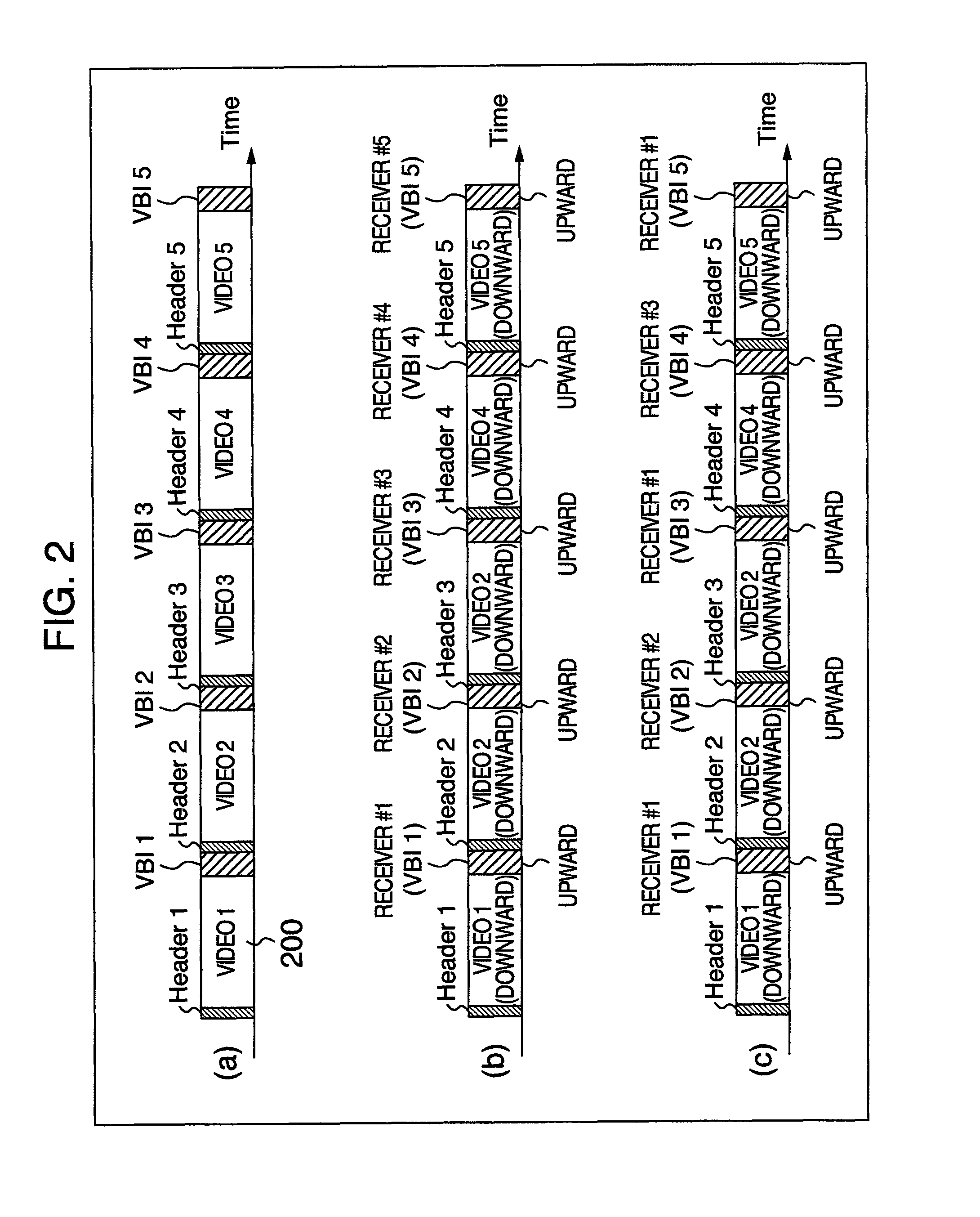
[0076]FIG. 12 schematically illustrates assignment made when the third embodiment is applied. In the example of FIG. 12, downward and upward transmissible regions are assigned to video signal periods and vertical retrace periods, respectively. Upward control commands are transferred during the vertical retrace periods. Downward control commands are transferred during the video signal periods. Assignment of downward control commands is made by multiplexing data that specify a corresponding wireless video receiver within a video signal sent by the wireless video transmitter.

[0077]Where the wireless transmitter sends contents such as movies, if five wireless video receivers are present within the wireless network as shown in FIG. 1, a state in which a single wireless video receiver can send out control commands appears every 41.7 ms×5=208.5 ms provided that the vertical scanning frequency of the video signal is 24 Hz (i.e., the vertical scanning period is 41.7 ms). That is, if N wirele...


PUM


Abstract

A technique is offered which is applied to a system for wirelessly sending and receiving control commands and which permits mutual communications owing to the control commands between a wireless video transmitter and wireless video receivers to be operated stably with low delay. The transmitter makes a decision as to whether commands received from the receivers are certain commands. If so, the transmitter assigns transmissible periods, in which the receivers can send commands, more preferentially to the wireless video receiver that has sent out the certain commands than the other wireless video receivers.

Description

INCORPORATION BY REFERENCE[0001]The present application claims priority from Japanese Patent Application JP2009-158362 filed on Jul. 3, 2009, the content of which is hereby incorporated by reference into this application.BACKGROUND OF THE INVENTION[0002]The present invention relates to a system for wirelessly sending video and audio signals from a video transmitter to plural video receivers and, more particularly, to a technique for communicating control commands and other commands between the video transmitter and the video receivers.[0003]A technique for sending video signals from a video transmitter to plural video receivers and transmitting control commands between the video transmitter and the video receivers is known, as described in JP-A-11-177965 in which there is disclosed a technique permitting peripheral devices to be controlled at all times by assigning regions for transmitting audio and video and regions for transmitting information for controlling the peripheral device...

Claims


Application Information

Patent Timeline
Patent Type & Authority Patents(United States)
IPC IPC(8): H04N7/173H04N21/4363H04N7/20H04N7/18H04N7/10
CPCH04N21/435H04N7/088H04N2005/4408H04N21/4122H04N2005/4407H04N5/4403H04N21/43637H04N7/106H04N7/20H04N21/42208H04N21/42204H04N21/41265
Inventor OGI, YUYAKABUTO, NOBUAKI
Owner MAXELL HLDG LTD
Why Eureka
Try Eureka