

Image forming apparatus and image forming method
- Summary
- Abstract
- Description
- Claims
- Application Information
AI Technical Summary
Benefits of technology
Problems solved by technology
Method used
Image

Examples
second embodiment
[0072]Referring now to FIGS. 8A, 8B, 9A, 9B, 10, 11A and 11B, an image forming apparatus and method in accordance with a second embodiment will now be explained. In view of the similarity between the first and second embodiments, the parts of the second embodiment that are identical to the parts of the first embodiment will be given the same reference numerals as the parts of the first embodiment. Moreover, the descriptions of the parts of the second embodiment that are identical to the parts of the first embodiment may be omitted for the sake of brevity.
[0073]FIG. 8A is a partial view showing the image forming apparatus of the second embodiment of the invention and is the same partial view as FIG. 3A, and FIG. 8B is an explanatory drawing viewed in the direction indicated by the arrow VIIIB of FIG. 8A. FIG. 9A is a view showing the second embodiment and is the same partial view as FIG. 4A, and FIG. 9B is an explanatory drawing viewed in the direction indicated by the arrow IXB of F...
third embodiment
[0083]Referring now to FIGS. 12A and 12B, an image forming apparatus and method in accordance with a third embodiment will now be explained. In view of the similarity between the second and third embodiments, the parts of the third embodiment that are identical to the parts of the second embodiment will be given the same reference numerals as the parts of the second embodiment. Moreover, the descriptions of the parts of the third embodiment that are identical to the parts of the second embodiment may be omitted for the sake of brevity.
[0084]FIG. 12A is an explanatory view showing a signal in the sequence control for an intermediate transfer belt driving motor 34 and the second transfer roller driving motor 35 of the image forming apparatus of the third embodiment, and FIG. 12B is a flow chart showing a management of the intermediate transfer belt 8 until the intermediate transfer belt driving motor 34 is turned off.
[0085]The third embodiment is directed to when the intermediate tran...
fourth embodiment
[0091]Referring now to FIGS. 13A, 13B, 14, 15A and 15B, an image forming apparatus and method in accordance with a fourth embodiment will now be explained. In view of the similarity between the previous embodiments and the fourth embodiment, the parts of the fourth embodiment that are identical to the parts of the previous embodiments will be given the same reference numerals as the parts of the previous embodiment. Moreover, the descriptions of the parts of the fourth embodiment that are identical to the parts of the previous embodiments may be omitted for the sake of brevity.
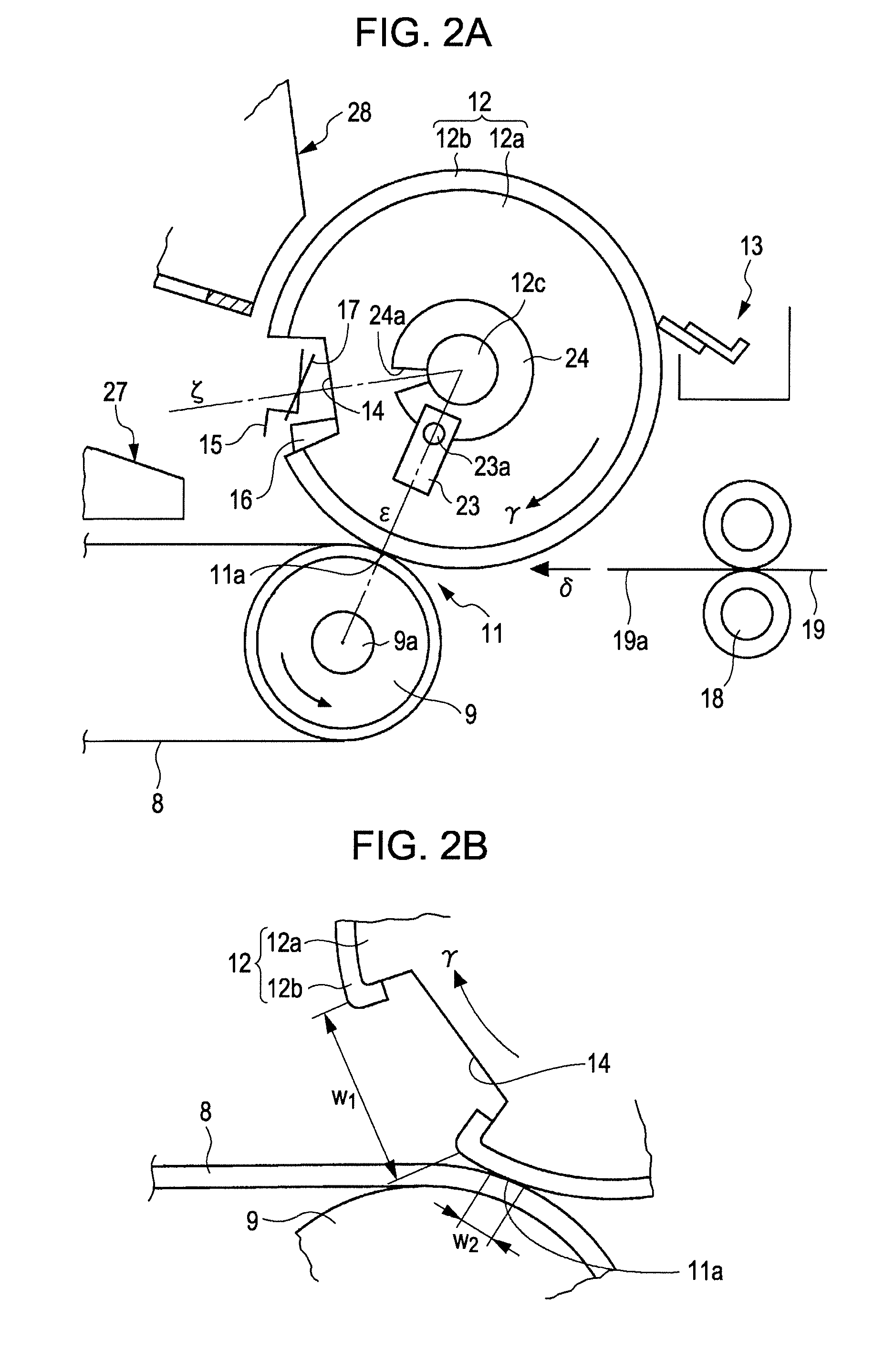
[0092]FIG. 13A is a partial view similar to FIG. 2A showing a second transfer section of the fourth embodiment of the image forming apparatus of the invention, and FIG. 13B is an explanatory drawing a detection of the transfer material presence. FIG. 14 is a block diagram similar to FIG. 10 showing the control for each of the second transfer roller driving motor 34 and the intermediate transfer belt driving mo...
PUM
 Abstract
Description
Claims
Application Information