Vacuum assisted wound dressing

a technology of wound dressing and vacuum tube, which is applied in the field of portable tnp therapy equipment, can solve the problems of not being able to transfer fluid to the vacuum tube, and not being able to achieve the most appropriate solution

Active Publication Date: 2011-01-13
SMITH & NEPHEW INC
View PDF110 Cites 139 Cited by
  • Summary
  • Abstract
  • Description
  • Claims
  • Application Information

AI Technical Summary

Problems solved by technology

However, for wounds of surface area below approximately 200 cm2 or internal volumes below about 1000 cm3 these solutions may not be the most appropriate since exudate volumes and exudate rates from these wounds may be managed by more traditional wound dressings, requiring dressing change every 3-7 days.
The relatively small dimensions of such wounds do not make them attractive for the traditional TNP therapies disclosed in the prior art; these devices typically including a remote vacuum source, fluid transfer lumen and remote fluid collection receptacle, control and power source and are of dimensions and weight exceeding those convenient or discrete for the patient to carry.
To facilitate fluid flow, a hydrophobic filling has been deemed particularly desirable by workers in the field and absorbent fillers as being particularly undesirable due to their hindering fluid transport.
The apparatus relies upon a wound contacting element that does not allow the transport of fluid beyond itself under the range of negative pressures being applied to the wound.
Alternatively, the wound contacting element may comprise entirely, or in part, a suitable material structured such that it can absorb wound exudate but does not allow transmission of this fluid to the vacuum tube.
This is a particular problem with particulate or fibrous so-called superabsorbent materials, for they can pass, even when fully saturated with fluid, through very small apertures of a size below which vacuum levels cannot be efficiently maintained.
However, dependent upon the configuration of the wound contacting element, the bore of the tube may be such that it is incapable of transmitting dry or hydrated components of the wound contacting element.
When devices comprised, at least in part, of the compositions are immersed in a fluid, they absorb fluid, become swollen and self-coalesce across contact points.

Method used


Image

  • Vacuum assisted wound dressing
  • Vacuum assisted wound dressing
  • Vacuum assisted wound dressing

Examples


example 5

Water Absorbency of Self-Coalescing Carboxymethylchilosan Fibres

[0101]The material resulting from Example 3 (100 mg) was immersed in water (4 ml) for 1 minute and withdrawn. Excess liquid was allowed to drain and then the hydrated transparent mass was weighed. The material was calculated to absorb approximately 25-times its own mass in water without significant dissolution.

example 6

Serum Absorbency of Self-Coalescing Carboxymethylchitosan Fibres

[0102]The material resulting from Example 3 (100 mg) was immersed in serum (4 ml) for 1 minute and withdrawn. Excess liquid was allowed to drain and then the hydrated transparent mass was weighed. The material was calculated to absorb approximately 13-times its own mass in serum without significant dissolution.

example 7

Self-Coalescence of Carboxymethylchitosan Fibres in Water

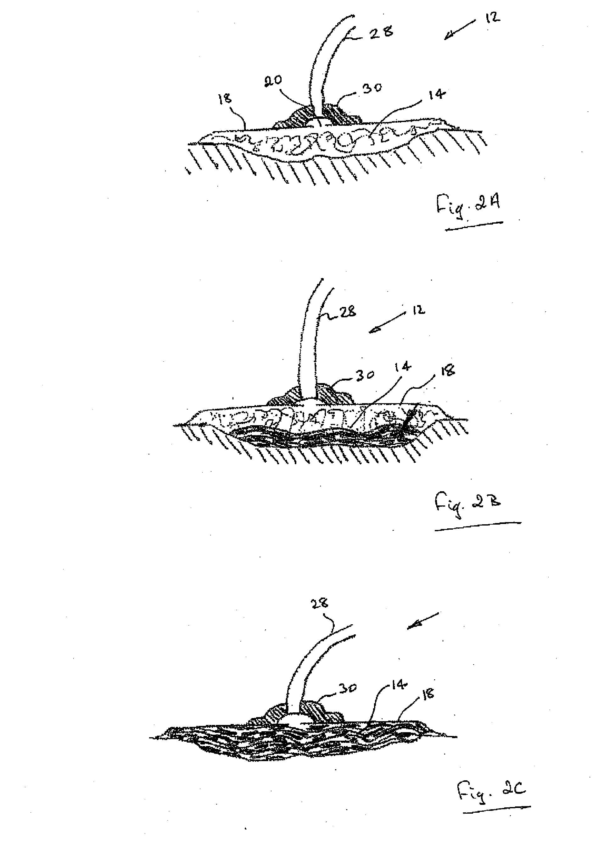
[0103]The material resulting from Example 3 (100 mg) was immersed in water (4 ml) for 1 minute and withdrawn. Excess liquid was allowed to drain and then the hydrated transparent mass was allowed to stand for 4 hours. After this time, the individual fibres of the material had self-coalesced and the material was then effectively a homogeneous, elastic hydrogel, able to stably retain its physical geometry under loading (FIG. 2).


PUM


Abstract

Apparatus for the application of topical negative pressure therapy to a wound site is described, the apparatus comprising: a wound contacting element for retaining wound exudate fluid therein; a wound covering element that provides a substantially airtight seal over the wound contacting element and wound site; a vacuum connection tube connecting a wound cavity to a vacuum source; and a vacuum source connected to a distal end of the vacuum connection tube.

Description

[0001]The present invention relates to a topical negative pressure (TNP) assisted wound dressing particularly, though not exclusively, for the treatment of wounds of relatively low area and / or relatively low volume.[0002]The subject of this invention is an apparatus for the management of small to medium sized wounds that utilises a vacuum source but manages wound exudate in a traditional manner by utilising an absorbent self-cohesive material in the wound cavity. No fluid is exported from the locality of the wound cavity other than by local evaporation. In this manner, an extremely portable system, of minimal inconvenience to the wearer, can be generated.BACKGROUND TO THE INVENTION[0003]TNP therapy has enjoyed relatively recent commercial success. WO9605873 and its family members describes a portable TNP therapy apparatus. The apparatus described mechanically supports tissue in the vicinity of the wound site and tissue mechanics and the rate of exudation from such sites requires a s...

Claims


Application Information

Patent Timeline
Patent Type & Authority Applications(United States)
IPC IPC(8): A61M1/00
CPCA61F13/02A61F2013/00536A61F2013/0094A61F13/00068A61M1/0088A61M39/24A61M1/0092A61M1/0049A61F13/00008A61F13/0216A61F13/0253A61F13/0266A61M1/78A61M1/985A61F13/0206A61F13/0209A61F13/0226A61M1/915A61M1/964
Inventor GREENER, BRYAN
Owner SMITH & NEPHEW INC
Why Eureka
Try Eureka