Image encoding device and image decoding device

a technology of image encoding and decoding device, which is applied in the direction of instruments, electrical appliances, computing, etc., can solve the problems of reducing the inter-frame compression efficiency, reducing the compression efficiency, and increasing the process delay, so as to prevent the compression efficiency from lowering, improve the uneven distribution of graphic patterns, and level the compression difficulty

Active Publication Date: 2011-01-20
PANASONIC CORP
View PDF3 Cites 17 Cited by
  • Summary
  • Abstract
  • Description
  • Claims
  • Application Information

AI Technical Summary

Benefits of technology

[0026]According to the present invention, at least one image fragment is swapped with another between N partial images, and it is therefore possible to improve the uneven distribution of graphic patterns between spatially-divided partial images, and to level the compression difficulty between partial images. Even with a compression scheme that highly utilizes the correlation between adjacent pixels within a frame, adjacent pixels are not referenced across slice boundaries. Therefore, if the image fragment division boundaries coincide with the slice boundaries, it is possible to prevent the compression efficiency from lowering due to spatial image division.

Problems solved by technology

However, since the motion picture compressing / encoding process is a technique for efficiently reducing the amount of data by utilizing the spatial and temporal correlation between frames, the division process for parallelization may lower the compression efficiency.
However, it is necessary, for the groups of frames to be independently processed in parallel, that frames of different groups do not reference one another, thus lowering the inter-frame compression efficiency.
Processing a plurality of GOPs in parallel requires a large-capacity frame buffer memory, thus increasing the process delay.
Since an increase in the process delay makes more difficult the code quantity control of controlling the quantity of code generated to be a predetermined quantity, there are only limited conditions under which the temporal division can be used for parallel processing.
If an input video is spatially divided into pieces for parallel compression / encoding by a known method, the compression / encoding difficulty varies between the spatially-divided partial images because the partial images contain different graphic patterns from one another.
It is very difficult to control the quantity of code so that a predetermined total quantity of code will be generated eventually for all partial images while independently processing the individual partial images in parallel.
However, at the boundary between partial images, it is not possible to use the correlation between pixels belonging to different partial images even if the pixels are spatially adjacent to each other.
Therefore, if the spatial image division is used with MPEG-4 AVC / H.264, it is not possible to avoid a decrease in the intra-frame compression efficiency that is even more significant than those with more traditional compression schemes.

Method used


Image

  • Image encoding device and image decoding device
  • Image encoding device and image decoding device
  • Image encoding device and image decoding device

Examples


embodiment 1

(1-1. Configuration of Image Encoding Device)

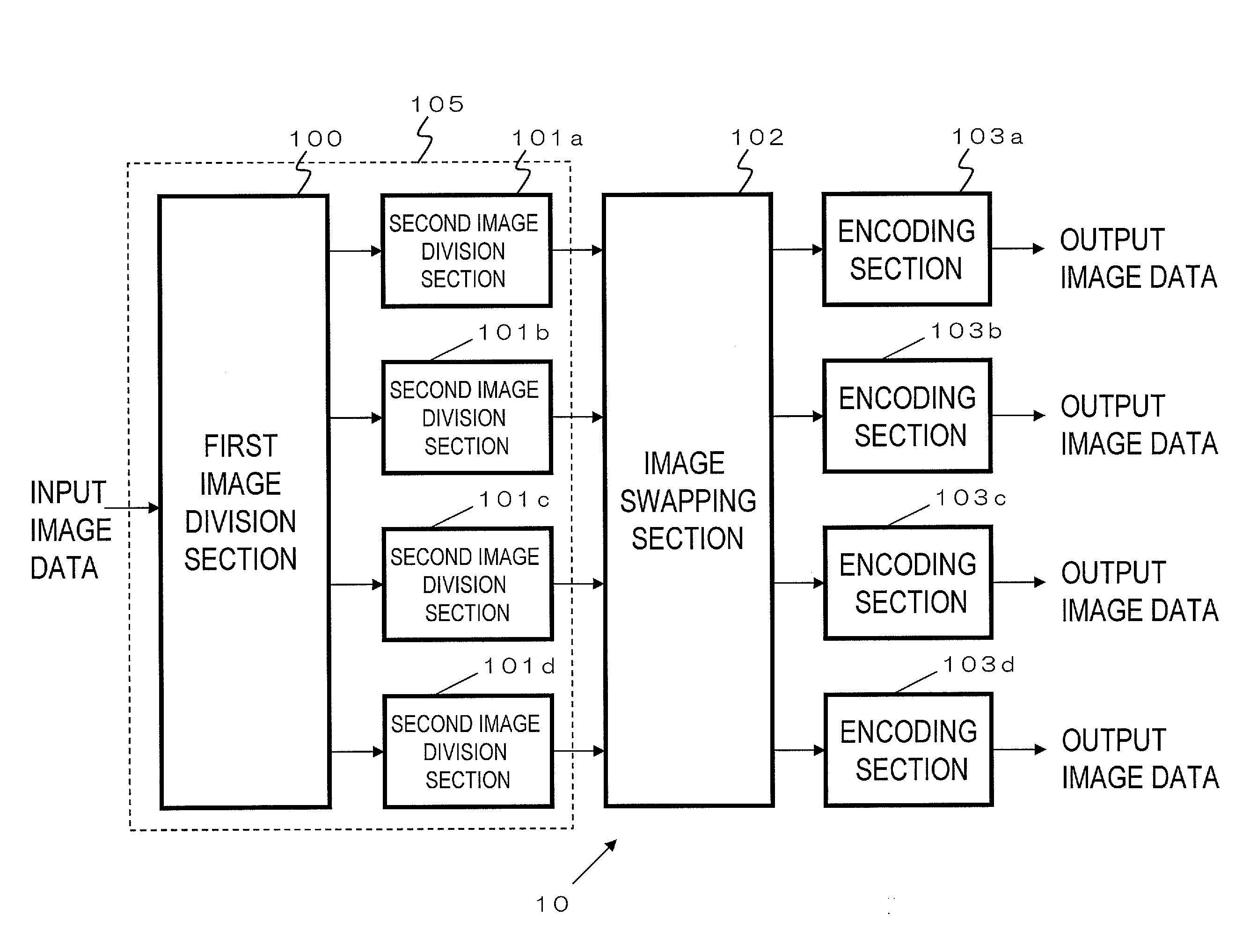
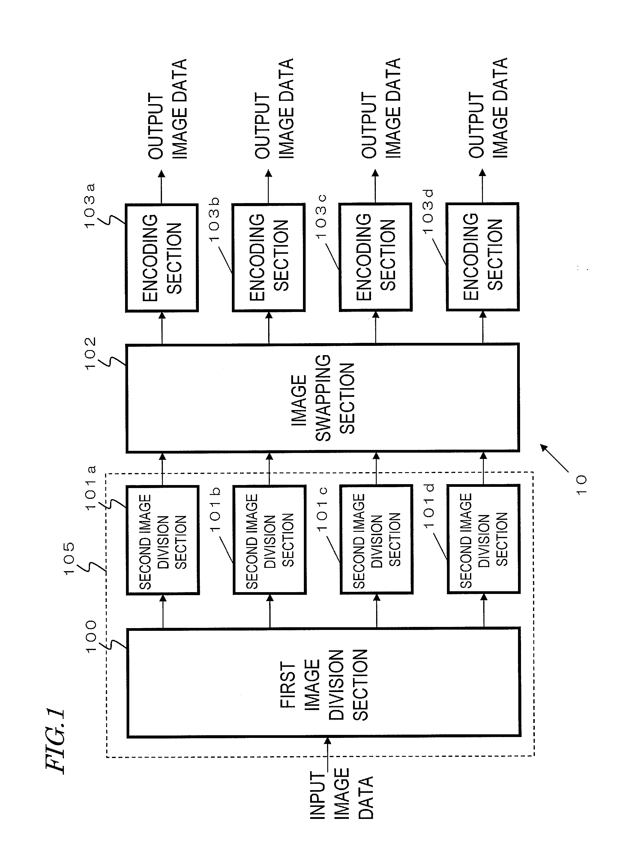
[0049]FIG. 1 is a block diagram showing a configuration of an image encoding device 10 of the present embodiment. The image encoding device 10 includes a first image division section 100, second image division sections 101a to 101d, an image swapping section 102, and encoding sections 103a to 103d.

[0050]The first image division section 100 receives image data. The first image division section 100 spatially divides the received image data into image data each of an appropriate size. The data of divided images (hereinafter referred to as “partial images”) are encoded in parallel in the encoding sections 103a to 103d after subsequent processes.

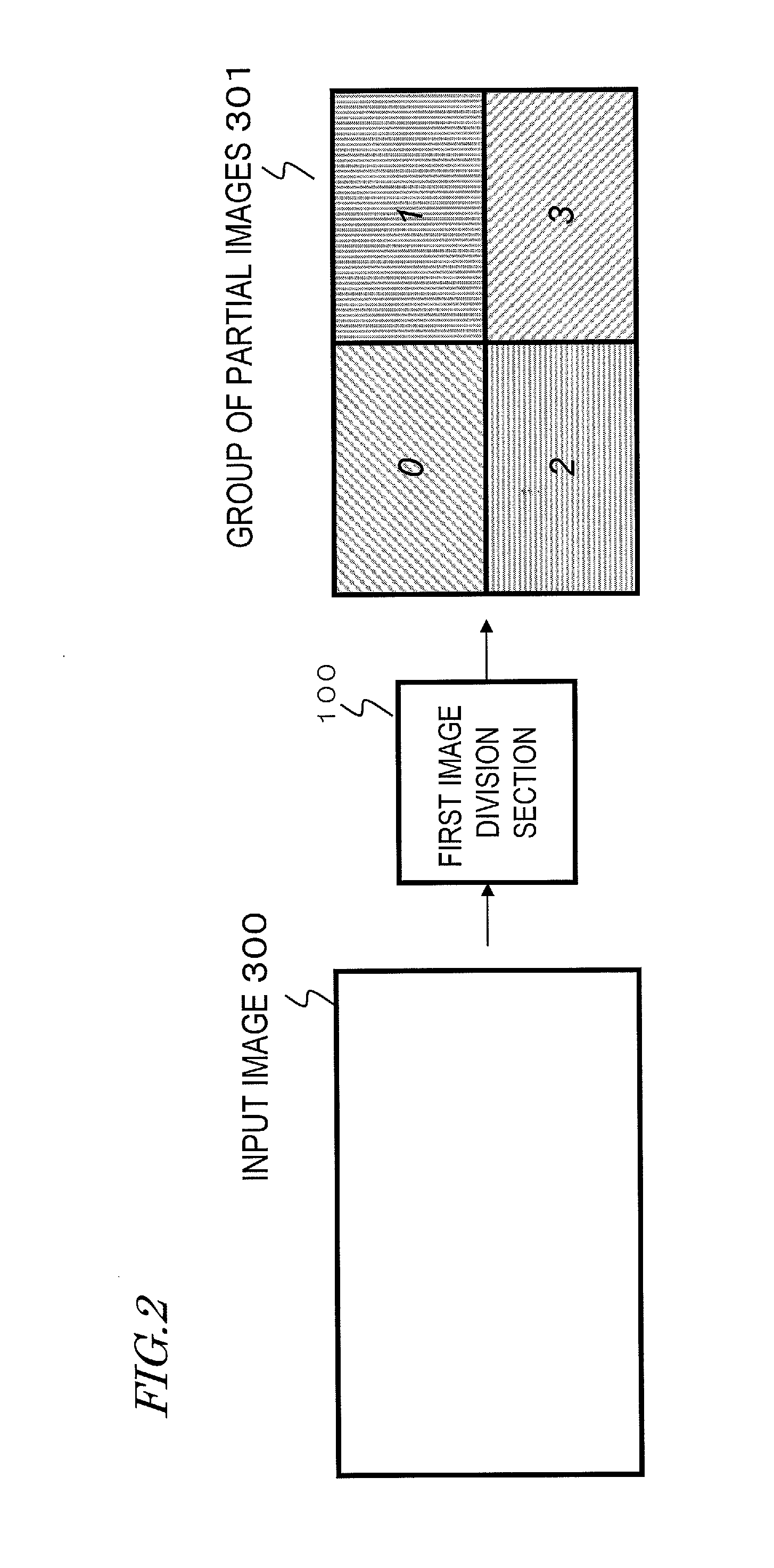
[0051]FIG. 2 schematically shows the process of the first image division section 100. The first image division section 100 receives image data of an input image 300, and performs a spatial division process. A group of four partial images 301 is obtained as a result of the division process. In the pres...

embodiment 2

[0082]The second image division sections 101a to 101d of Embodiment 1 generate strip-shaped image fragments.

[0083]The second image division sections 101a to 101d of the present embodiment generate image fragments which are not strip-shaped. The discussion below will focus on the second image division sections 101a to 101d and the shape of the image fragments.

[0084]Note that the configuration of the image encoding device of the present embodiment is the same as that of the image encoding device 10 of Embodiment 1. Therefore, the image encoding device of the present embodiment will be described assuming that it is the “image encoding device 10” shown in FIG. 1.

[0085]Parts of the configuration and the operation of Embodiment 2 that are different from those of Embodiment 1 will be described below. Components and the operation thereof which are not mentioned below are the same as those of Embodiment 1.

[0086]FIG. 7 shows a division scheme for dividing partial images into pieces by the sec...

embodiment 3

[0099]The present embodiment is directed to an image encoding device in which an image expansion section is added to the configuration of the image encoding device 10 of Embodiment 1 or 2.

[0100]FIG. 11 shows a configuration of an image encoding device 20 of the present embodiment. In FIG. 11, like components of the image encoding device 20 to those of the image encoding device 10 of Embodiment 1 in terms of function are denoted by like reference numerals and will not be described below.

[0101]An image expansion section 900 has a function of expanding the size of the image of the input image data. The image size is expanded for the purpose of adjusting the size of the image of the input image data so as to obtain partial images of a size that can be processed by the encoding sections 103a to 103d. Where the size of the input image is not an integral multiple of an image size that can be processed by the encoding sections 103a to 103d, it is not possible, as it is, to obtain partial im...


PUM


Abstract

An image encoding device includes: an image division section for dividing one frame of image into a plurality of image fragments, grouping the plurality of image fragments into N sets (N: an integer of 2 or more), and outputting the N sets of image fragments as N partial images; an image swapping section for swapping at least one image fragment with another between the N partial images to thereby output N partial images each having shuffled image fragments; and an encoding section for encoding the N partial images output from the image swapping section.

Description

BACKGROUND OF THE INVENTION[0001]1. Field of the Invention[0002]The present invention relates to an image encoding device for dividing a high-resolution image into a plurality of partial images and compressing / encoding the partial images in parallel, and to an image decoding device for decoding the compressed / encoded image.[0003]2. Description of the Related Art[0004]A motion picture includes a sequence of frames. With codecs used in recording apparatus for use in broadcasting stations or for household use, a motion picture is compressed / encoded frame by frame or by using differences between frames, for example. The amount of calculation of a codec required for compression / encoding increases as the number of pixels of one frame (spatial resolution) and the frame rate (temporal resolution) increase.[0005]In order to compress / encode such a motion picture in real time, there are many methods known in the art in which the compression / encoding process is parallelized by spatially dividin...

Claims


Application Information

Patent Timeline
Patent Type & Authority Applications(United States)
IPC IPC(8): G06K9/36H04N19/00H04N19/119H04N19/134H04N19/176H04N19/196H04N19/436H04N19/86
CPCH04N19/88H04N19/61
Inventor SAITO, HIROSHI
Owner PANASONIC CORP
Why Eureka
Try Eureka