Surgical access device with moveable device port

Inactive Publication Date: 2011-01-20
V ALIGN
View PDF7 Cites 36 Cited by
  • Summary
  • Abstract
  • Description
  • Claims
  • Application Information

AI Technical Summary

Benefits of technology

[0015]The annular seal member can include two sealing portions or leaves, extending toward one another about the annu

Problems solved by technology

Because of size limitations, it is often necessary to utilize multiple access ports in a single procedure, distributed across the abdomen, for example.
However, with a conventional arrangement, simultaneous insertion of multiple instruments suffers from mutual interference between adjacent instruments and loss of insufflation pressure and ga

Method used


Image

  • Surgical access device with moveable device port
  • Surgical access device with moveable device port
  • Surgical access device with moveable device port

Examples


Embodiment Construction

[0040]Reference will now be made in detail to the presently preferred embodiments of the invention, examples of which are illustrated in the accompanying drawings.

[0041]As set forth hereinabove, the devices and related methods presented herein are particularly suited for laparoscopic procedures, in-particular for single-incision laparoscopic surgeries, or “SILS.” The subject devices provide various advantages, including but not limited to sealed simultaneous insertion of multiple instruments, as well as support and guidance of such instruments. Further, the guidance of such support is adjustable when inserted though a moveable device port.

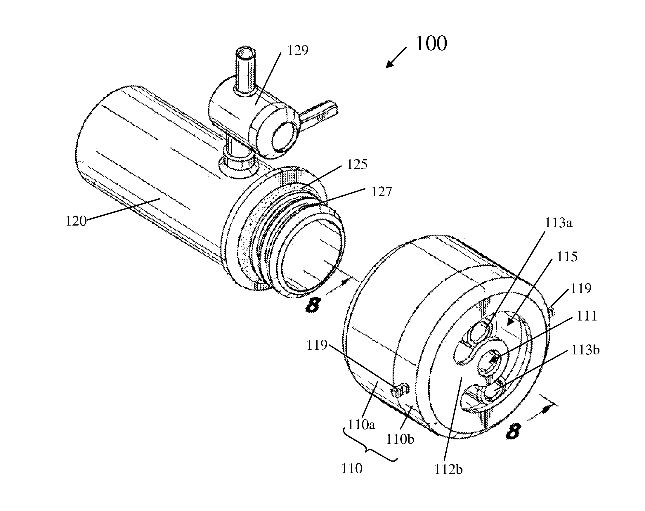
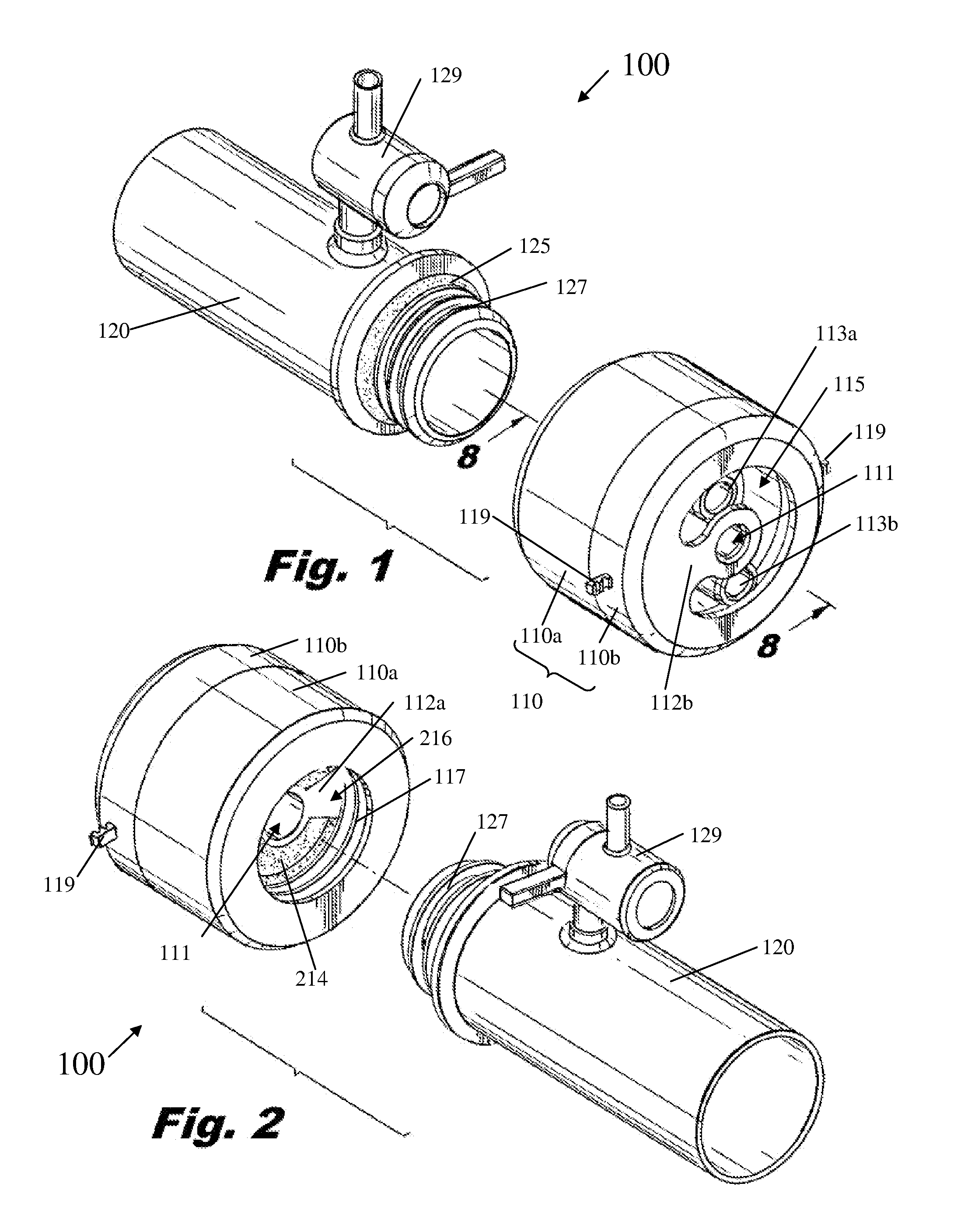
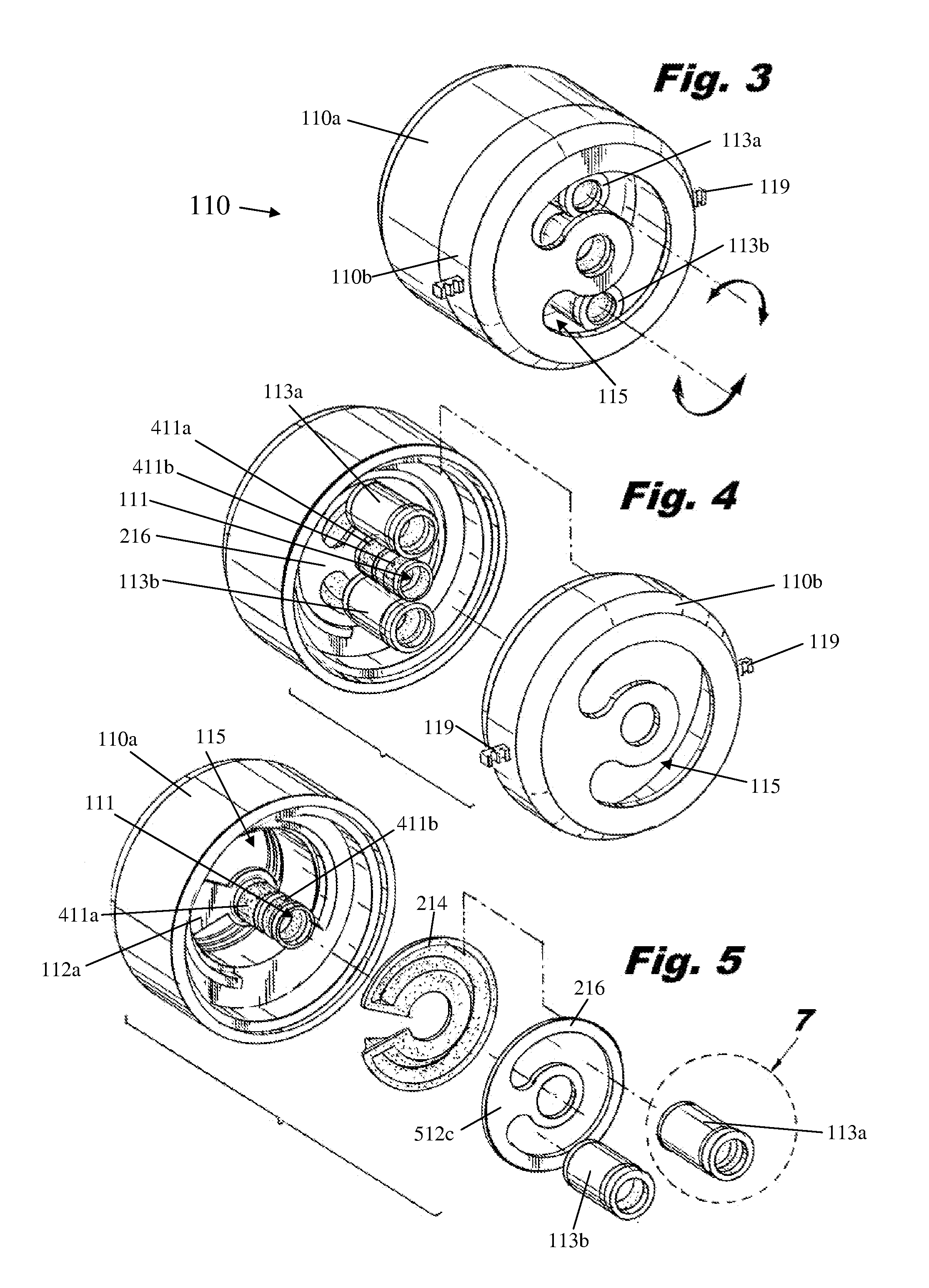
[0042]FIGS. 1-11 illustrate various aspects of a surgical access device in accordance with the present invention. FIGS. 1 and 2 illustrate, respectively, top and bottom isometric views of a surgical access device constructed in accordance with the invention, which is designated generally by reference number 100. A housing 110 and body tube 120 are ...


PUM


Abstract

A surgical access device for use in laparoscopic surgical procedures includes a housing portion and at least one moveable device port. The housing portion has an axial bore extending therethrough, defining a central axis of the surgical access device. The at least one moveable device port is moveable about an annular path corresponding to an annular seal member. Each moveable device port defines a lumen extending therethrough, and each lumen is substantially parallel to the central axis of the surgical access device.

Description

FIELD OF THE INVENTION[0001]The present invention relates to surgical access devices, such as those used in laparoscopic surgical procedures, typically within the abdominal cavity of the patient. Particularly, the present invention is directed to a surgical access device having at least one device port that is moveable with respect to a housing of the access device.DESCRIPTION OF RELATED ART[0002]A variety of surgical access devices are known in the art for maintaining an operative path through an anatomical structure, particularly a patient's abdominal wall, to facilitate insertion of surgical instruments during minimally-invasive (laparoscopic) surgical procedures. Typically, one or more instruments are inserted through such access devices into the peritoneal space, which is insufflated during a procedure, typically with an inert gas such as carbon dioxide. Such access devices maintain the incision opening and minimize trauma through repeated insertion and manipulation of instrume...

Claims


Application Information

Patent Timeline
IPC IPC(8): A61B1/32
CPCA61B1/32A61B17/3423A61B2017/3486A61B2017/3445A61B2017/3466A61B17/3462
Inventor RAVIKUMAR, SUNDARAMALWARD, ALLAN
Owner V ALIGN
Why Eureka
Try Eureka