
Tool

Inactive Publication Date: 2011-01-27
TOWNSEND RICHARD
View PDF6 Cites 4 Cited by
  • Summary
  • Abstract
  • Description
  • Claims
  • Application Information

AI Technical Summary

Benefits of technology

[0017]In a further embodiment, during use, the fulcrum point moves along said other surface so as to increase the leverage to said article gradually reducing the applied force thereto.

Problems solved by technology

Current tools for removing these parts have the tendency to damage the fasteners or peripheral parts of the automobile.

Method used


Image

  • Tool
  • Tool
  • Tool

Examples


Embodiment Construction

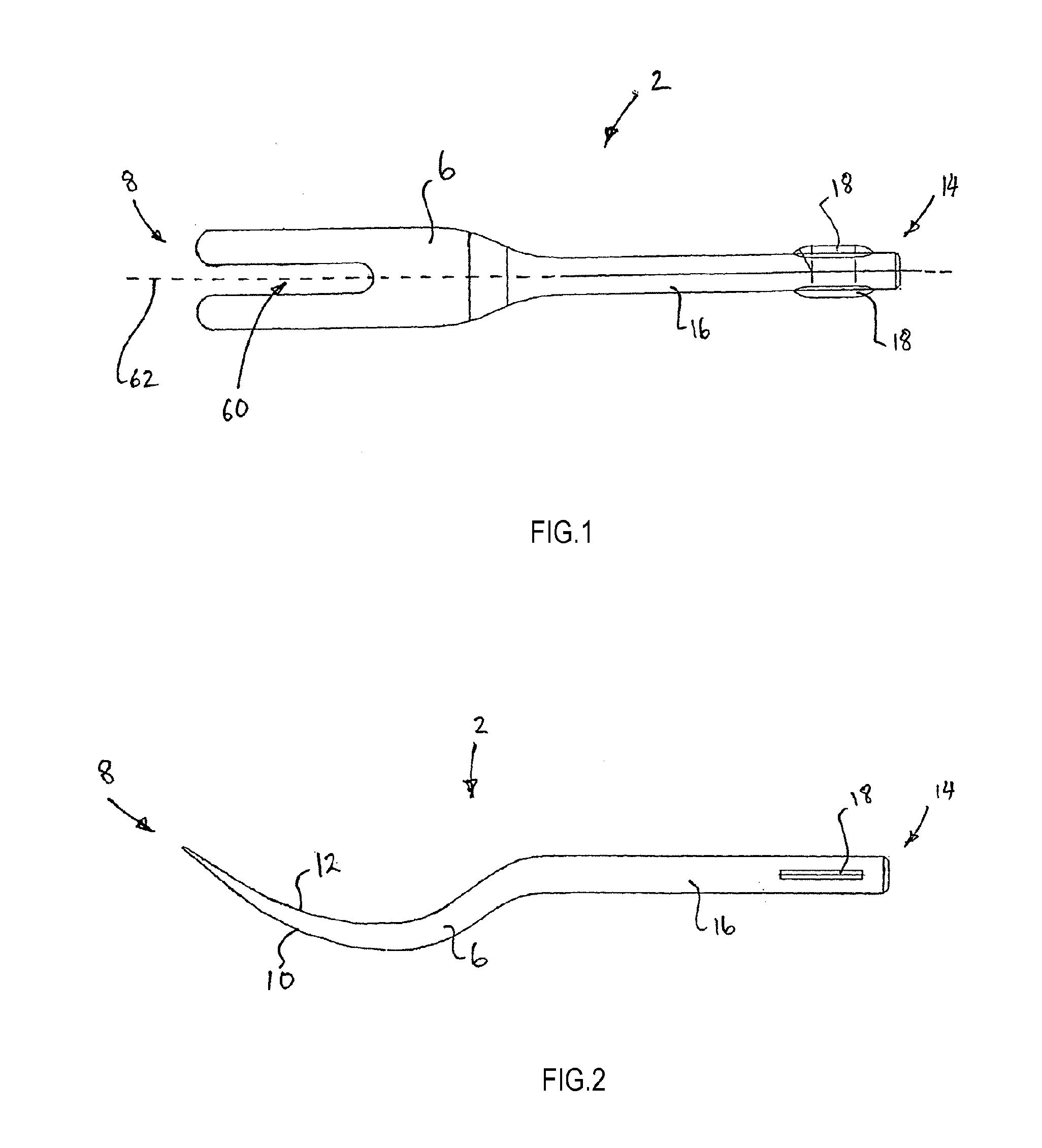
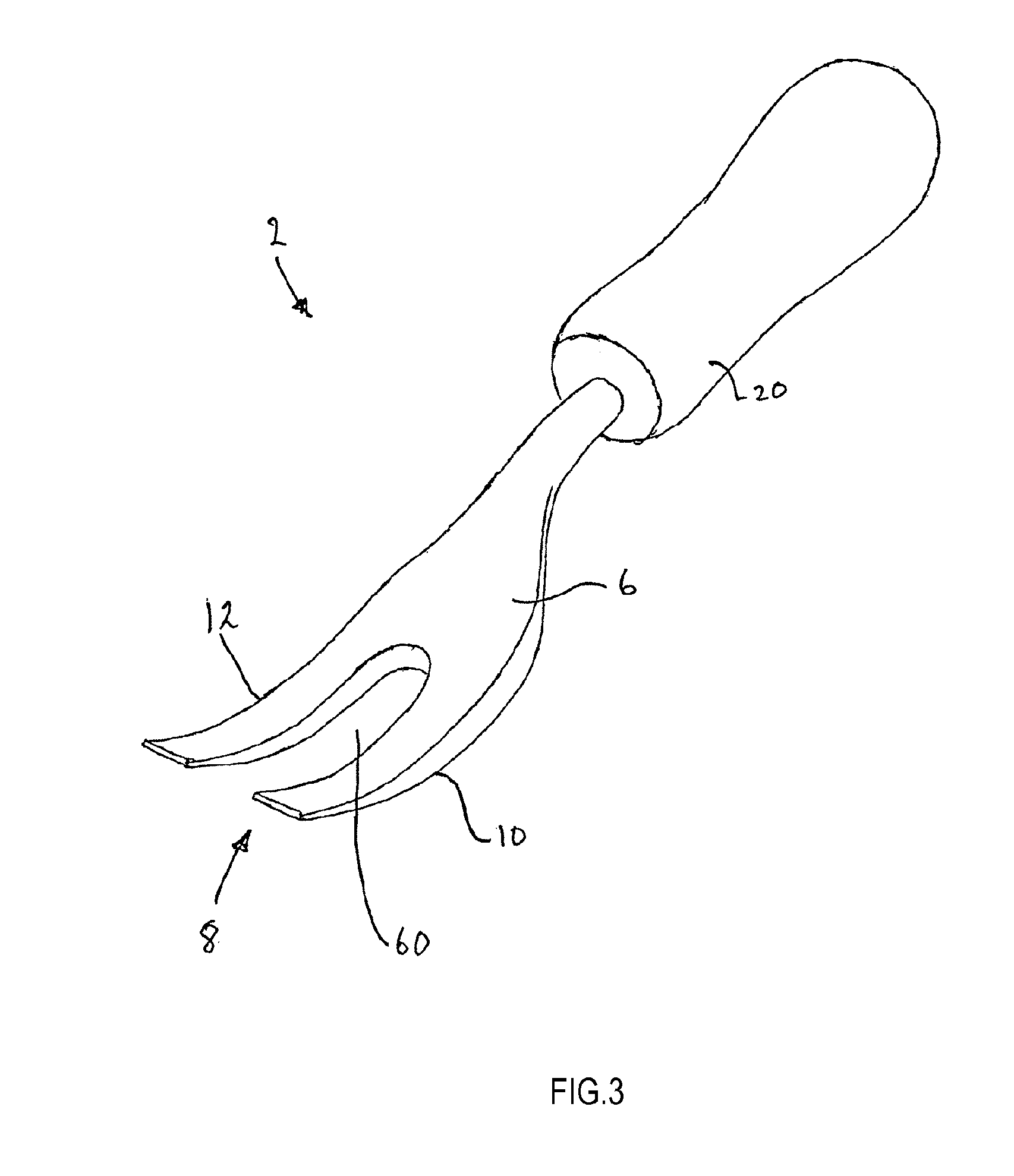
[0056]With reference to FIGS. 1 through 7 there is shown one embodiment of a tool 2 for manipulating or leveraging an article 4. The tool 2 comprises an operative portion 6 having a first end 8 and a convex surface 10 extending substantially therefrom. The convex surface comprises a first curved segment 24 (shown in FIG. 6) adjacent the first end 8 and has a radius greater than at least one further subsequent curved segment further defining the first curved surface 10.

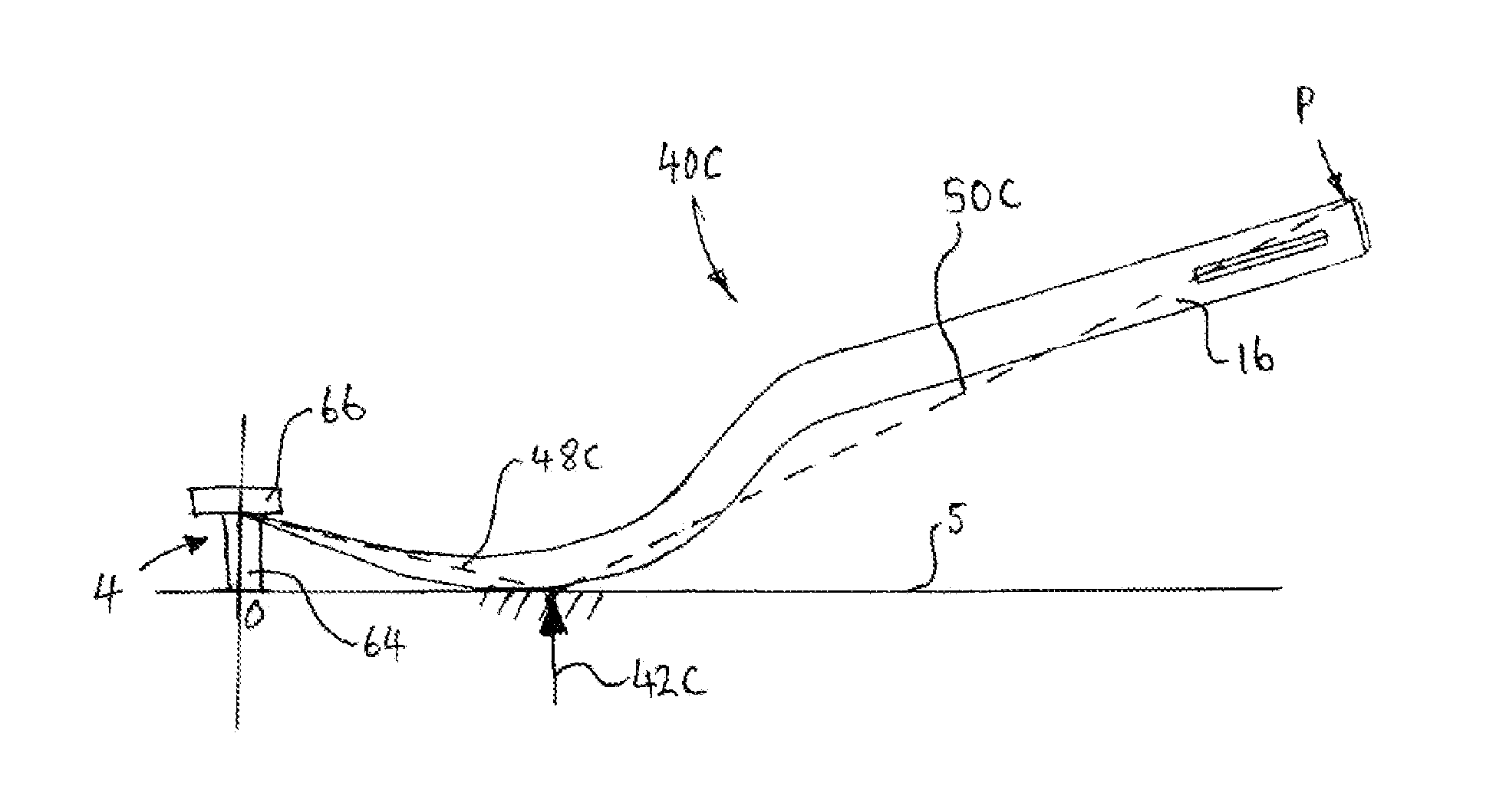
[0057]The operative portion 6 further comprises a concave surface 12 that is opposite the convex surface 10. When the tool 2 is in use, one of the convex 10 or concave 12 surfaces engages with the article 4 whereby the other of the convex 10 or concave 12 surfaces becomes in contact with a work-piece 5. Between both two contact points the convex 10 and concave 12 surfaces are co-operable so that a fulcrum point is established between the work-piece 5 and the contacting surface. During operation, the fulcrum point moves...


PUM

PropertyMeasurementUnit
Fractionaaaaaaaaaa
Fractionaaaaaaaaaa
Fractionaaaaaaaaaa

Abstract

A tool for manipulating an article includes an operative portion. The operative portion includes a convex surface defined by a first curved segment extending substantially from a first end having a radius greater than at least one further subsequent curved segment, and a concave surface opposite the convex surface. In use, one of the convex and concave surfaces is engageable with an article and the other of the convex and concave surfaces is engageable with a work-piece such that the convex and concave surfaces are cooperable to establish a fulcrum point between the work-piece and the other surface.

Description

FIELD OF THE INVENTION[0001]The present invention relates to a tool.BACKGROUND OF THE INVENTION[0002]Automobiles have many removable parts. Such parts include, but are not limited to, door trims, dashboard components, interior paneling, body protection moulding, badges and name plates, chrome strips, bumperbar inserts, inner guard liners, under bonnet insulators, boot linings, windscreen surrounds and the like. These are retained in position by a variety of fastening means such as plastic clips, trim plugs, metal spring clips, double sided tape, integrated clips and adhesives of various types.[0003]Current tools for removing these parts have the tendency to damage the fasteners or peripheral parts of the automobile.[0004]The present invention is intended to provide a new tool useful for, inter alia, assisting in the manipulation and / or removal of such fastening means so that such damage is minimised if not eliminated.[0005]It is to be understood that, if any prior art publication or...

Claims


Application Information

Patent Timeline
IPC IPC(8): B23P19/04B25C11/00
CPCB25C11/00B25B27/0035Y10T29/53896B66F15/00Y10T29/49822B25B27/14
Inventor TOWNSEND, RICHARD
Owner TOWNSEND RICHARD
Learn More