

Energy Generation Method and Apparatus by the Harnessing of Centrifugal Force
- Summary
- Abstract
- Description
- Claims
- Application Information
AI Technical Summary
Benefits of technology
Problems solved by technology
Method used
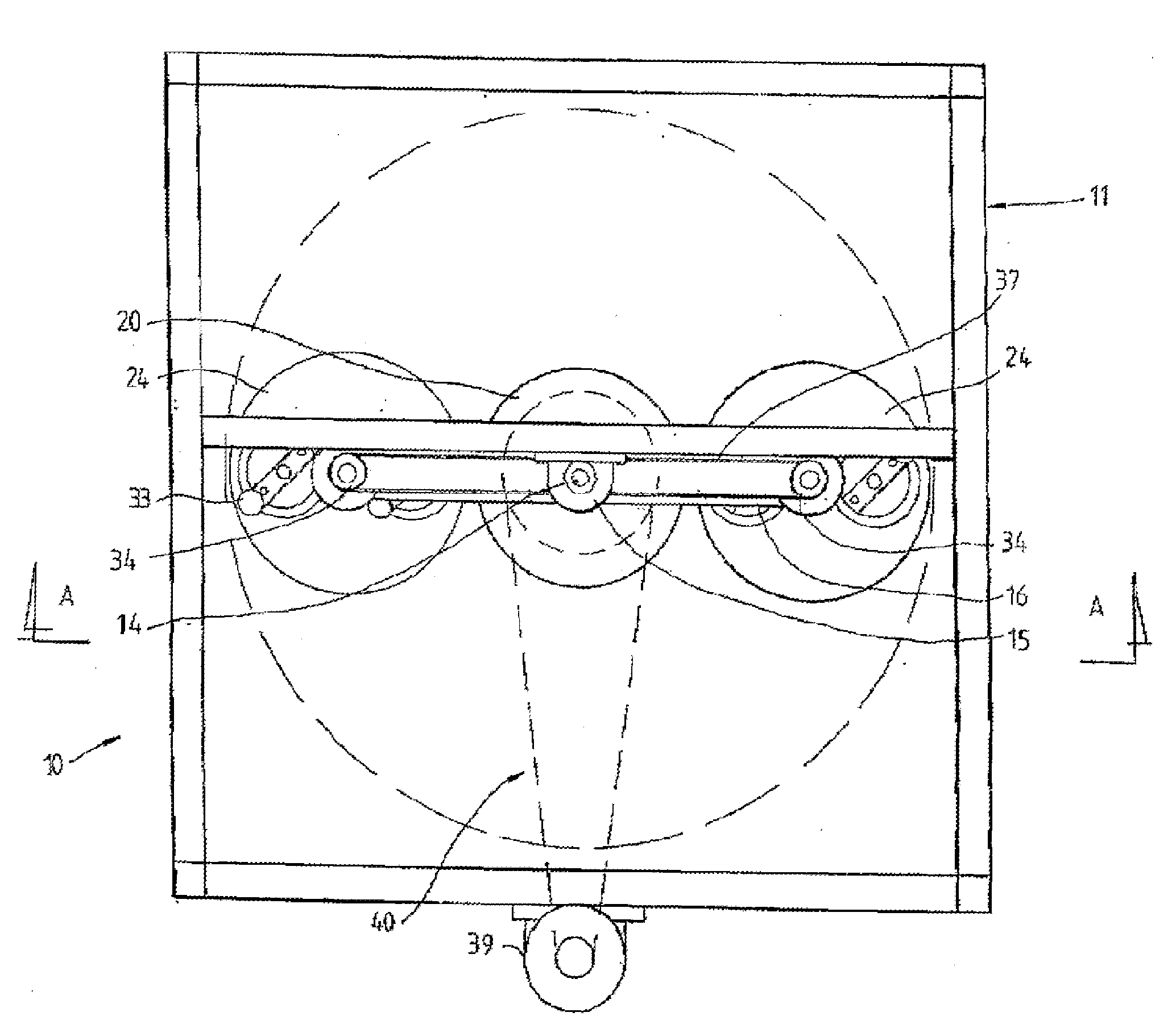
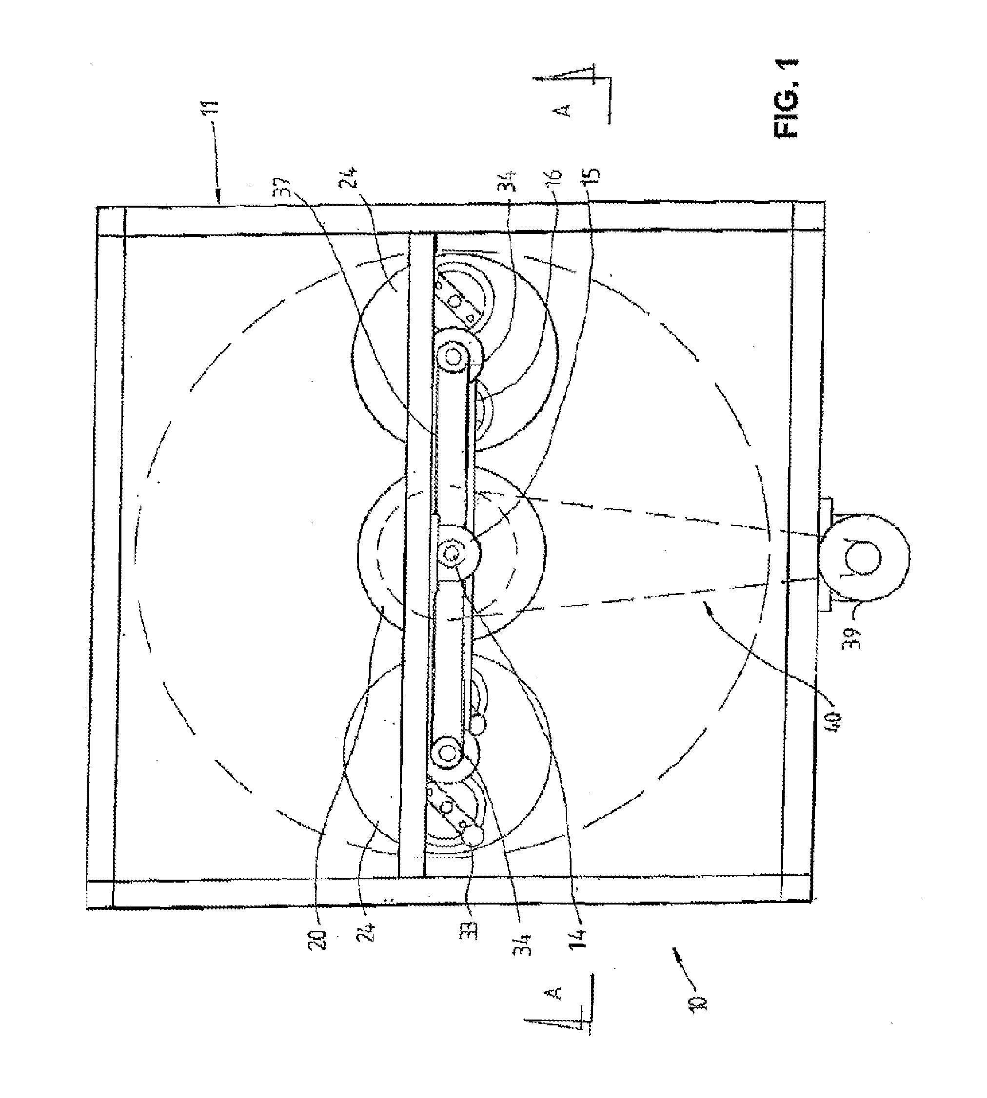
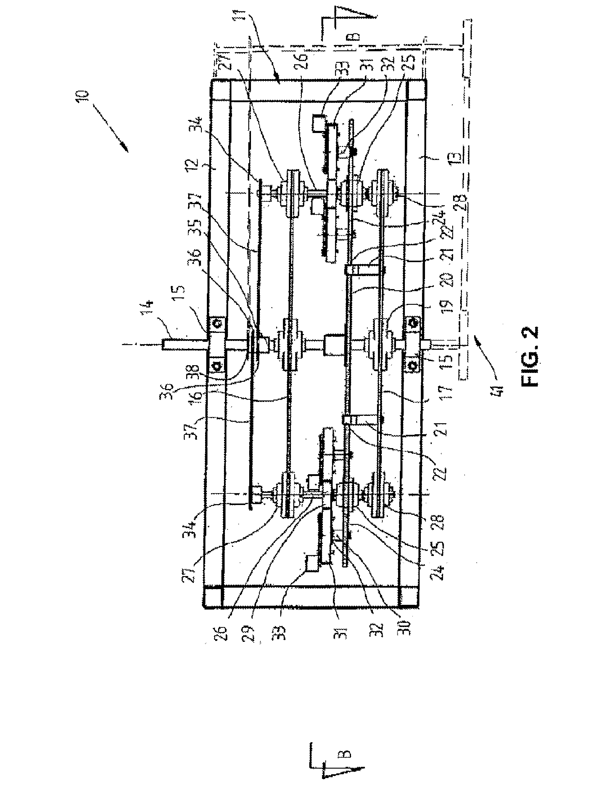
Image

Examples
Embodiment Construction
[0074]Some inventions can involve new discoveries. The mechanism causing gravitational force is not understood, but it is undeniable that it exists, so it is accepted. In the case of centrifugal force it is theorized that it is simply an apparent reaction to centripetal force, not a force in its own right. This is not proven. Centrifugal force is simply dismissed because the cause is not known or understood, while an explanation is postulated.
[0075]The accepted postulation is that centripetal force is applied at right angles to the rotating body and so applies a constant change in direction to the body without retarding it, and so does not retard angular momentum which is known to be a constant.
[0076]There is a flaw in this hypothesis. It is that a change in direction can only result from an external force. In the case of a centripetal inward force / pull applied at right angles it can only be caused by an inward movement, which must require a shortening of the tether, which does not ...
PUM
 Abstract
Description
Claims
Application Information