Electrical Cable Shroud

a technology of electric cables and shrouds, which is applied in the manufacture of engines, mechanical equipment, machines/engines, etc., can solve the problems of affecting the performance of the engine,

Inactive Publication Date: 2011-01-27
GENERAL ELECTRIC CO
View PDF30 Cites 40 Cited by
  • Summary
  • Abstract
  • Description
  • Claims
  • Application Information

AI Technical Summary

Problems solved by technology

Inlet guide vane assemblies, along with other structural elements of aircraft and aircraft engines, such as struts, may be susceptible of forming ice accumulation under certain operating and environmental conditions.
Ice acc

Method used


Image

  • Electrical Cable Shroud
  • Electrical Cable Shroud
  • Electrical Cable Shroud

Examples


Embodiment Construction

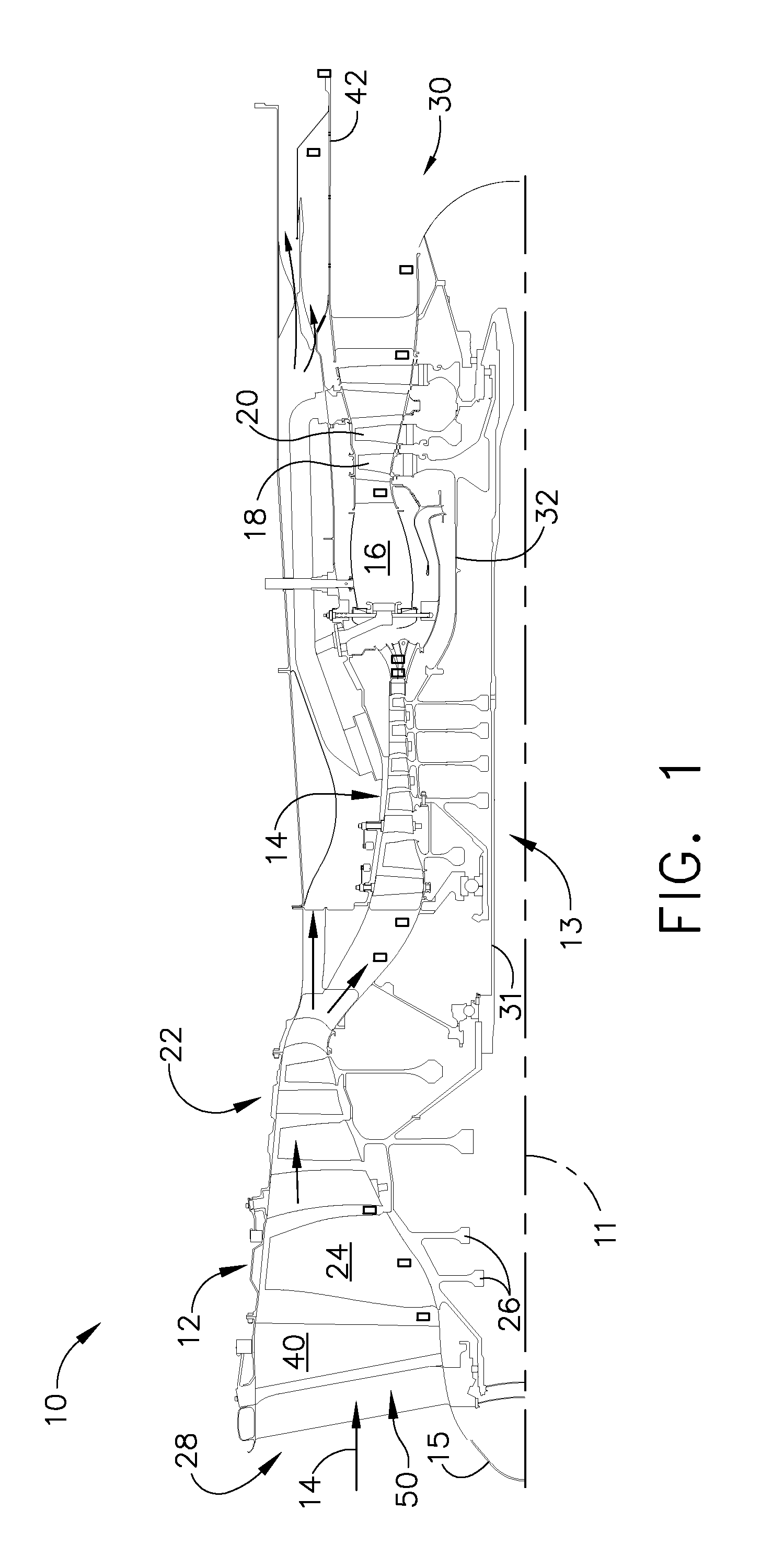
[0017]FIG. 1 is a cross-sectional schematic illustration of an exemplary gas turbine engine assembly 10 having a longitudinal axis 11. Gas turbine engine assembly 10 includes a fan assembly 12 and a core gas turbine engine 13. Core gas turbine engine 13 includes a high pressure compressor 14, a combustor 16, and a high pressure turbine 18. In the exemplary embodiment, gas turbine engine assembly 10 also includes a low pressure turbine 20, and a multi-stage booster compressor 22.

[0018]Fan assembly 12 includes an array of fan blades 24 extending radially outward from a rotor disk 26. Gas turbine engine assembly 10 has an intake or inlet side 28 and an exhaust side 30. Fan assembly 12, booster 22, and turbine 20 are coupled together by a first rotor shaft 31, and compressor 14 and turbine 18 are coupled together by a second rotor shaft 32.

[0019]In operation, air flows through fan assembly 12 and booster 22. The compressed air that is discharged from booster 22 is channeled through comp...


PUM


Abstract

An electrical cable shroud forming an annular structure having an outer surface and an inner surface, the cable shroud comprising a substantially J-shaped cross-section having a longest side, a shorter leg, and a rounded portion therebetween. The longest side of the J forms the outer surface and the shorter leg forms the inner surface. The shorter leg turns inwardly and terminates in a tab extension substantially perpendicular to the outer surface, and the rounded portion forms an internal space suitable for enclosing electrical components.

Description

CROSS-REFERENCE TO RELATED APPLICATION[0001]This application claims priority to U.S. Provisional Application Ser. No. 61 / 228,462, filed Jul. 24, 2009.STATEMENT REGARDING FEDERALLY SPONSORED RESEARCH & DEVELOPMENT[0002]The US Government may have certain rights in this invention pursuant to Contract No. N00019-96-C-0176 awarded by the US Department of the Air Force.BACKGROUND OF THE INVENTION[0003]The technology described herein relates generally to electrical devices, particularly to electrical devices for supporting and securing electrical cables, and more particularly, to electrical cable shrouds.[0004]Many gas turbine engine assemblies include a fan assembly that is mounted upstream from a core gas turbine engine. During operation, a portion of the airflow discharged from the fan assembly is channeled downstream to the core gas turbine engine wherein the airflow is further compressed. The compressed airflow is then channeled into a combustor, mixed with fuel, and ignited to genera...

Claims


Application Information

Patent Timeline
IPC IPC(8): F02C7/20H02G3/04
CPCF02C7/00H02G3/0487F05D2250/70Y02T50/672H02G3/30Y02T50/60
Inventor WOELKE, SARAH ANNWORMUTH, JEFFERY BLAKE
Owner GENERAL ELECTRIC CO
Why Eureka
Try Eureka