Sling Fittings and Sling System for a Firearm

a technology for sling fittings and firearms, applied in the field of sling fittings and sling systems for firearms, can solve the problems of requiring constant hands-on control of weapons, affecting weapon use in dynamic combat environments, and affecting the use of weapons, so as to achieve greater articulation of connection structures, greater freedom of movement, and greater range of movement

Active Publication Date: 2011-01-27
MAGPUL INDUSTRIES
View PDF49 Cites 19 Cited by
  • Summary
  • Abstract
  • Description
  • Claims
  • Application Information

AI Technical Summary

Benefits of technology

[0012]In use, a point-type sling mount is attached to the connection bar. This type of mount is essentially a clip or link that attaches the sling to the weapon. Being a non-threaded, mechanical interface, the point-type mount will be able to slide along the connection bar to either the left or right side. This interface structure then allows a user to hold the weapon in either a left-handed or a right-handed stance and generally allows more freedom of movement with the weapon, overcoming the drawbacks of the prior art. An auxiliary link may be present on the bar so that the sling may be attached to said link for greater articulation of the connection structure and, therefore, greater range of movement.
[0013]The sling then, will clip on the point-type sling fitting and a forward sling mount. When desired, the user may unclip the forward connection from the forward sling mount and position it on a specialized loop on the sling body for a one-point mounting centered upon the said sling fitting. The sling also presents a quick adjustment configuration by having a sliding buckle which controls strap length and is attached to a loop handle for easy manual operation.

Problems solved by technology

While it offers the user the ability to carry the weapon comfortably over the shoulder or securely across the back, the traditional, bottom-mounted 2-point sling hinders weapon usage in dynamic combat environments since the weapon is stowed in a non-useable orientation.
Additionally due to the amount of strap material used to wrap around the body they can also interfere with chest-mounted equipment, such as on load-bearing vests.
However, one disadvantage of the point-type sling is that it requires constant hands-on control of the weapon during movement as otherwise it will swing like a pendulum and may become unwieldy when not in use.
Furthermore due to the instability of this configuration, it is not optimized for comfortable carrying of the weapon over long periods of time or long distances.
However, even with the advent of the convertible sling system, there still exists a major limitation: the ability to rapidly transition the weapon from side-to-side without additional manual operations.
The lack of this capability is particularly hazardous when hunting for a hidden enemy as, when looking around corners and other obstacles, a soldier must occasionally expose his or her body to obtain an appropriate look.
In order to effectively look, the sling must be extended to its largest possible configuration or the soldier must simply remove the sling, which both eliminates its usefulness and creates a tangling hazard.
Being along one side of the weapon, then, presents the adaptability difficulties presented above.

Method used


Image

  • Sling Fittings and Sling System for a Firearm
  • Sling Fittings and Sling System for a Firearm
  • Sling Fittings and Sling System for a Firearm

Examples


Embodiment Construction

[0055]With reference now to the drawings, the preferred embodiment of the sling fitting is herein described. It should be noted that the articles “a”, “an”, and “the”, as used in this specification, include plural referents unless the content clearly dictates otherwise.

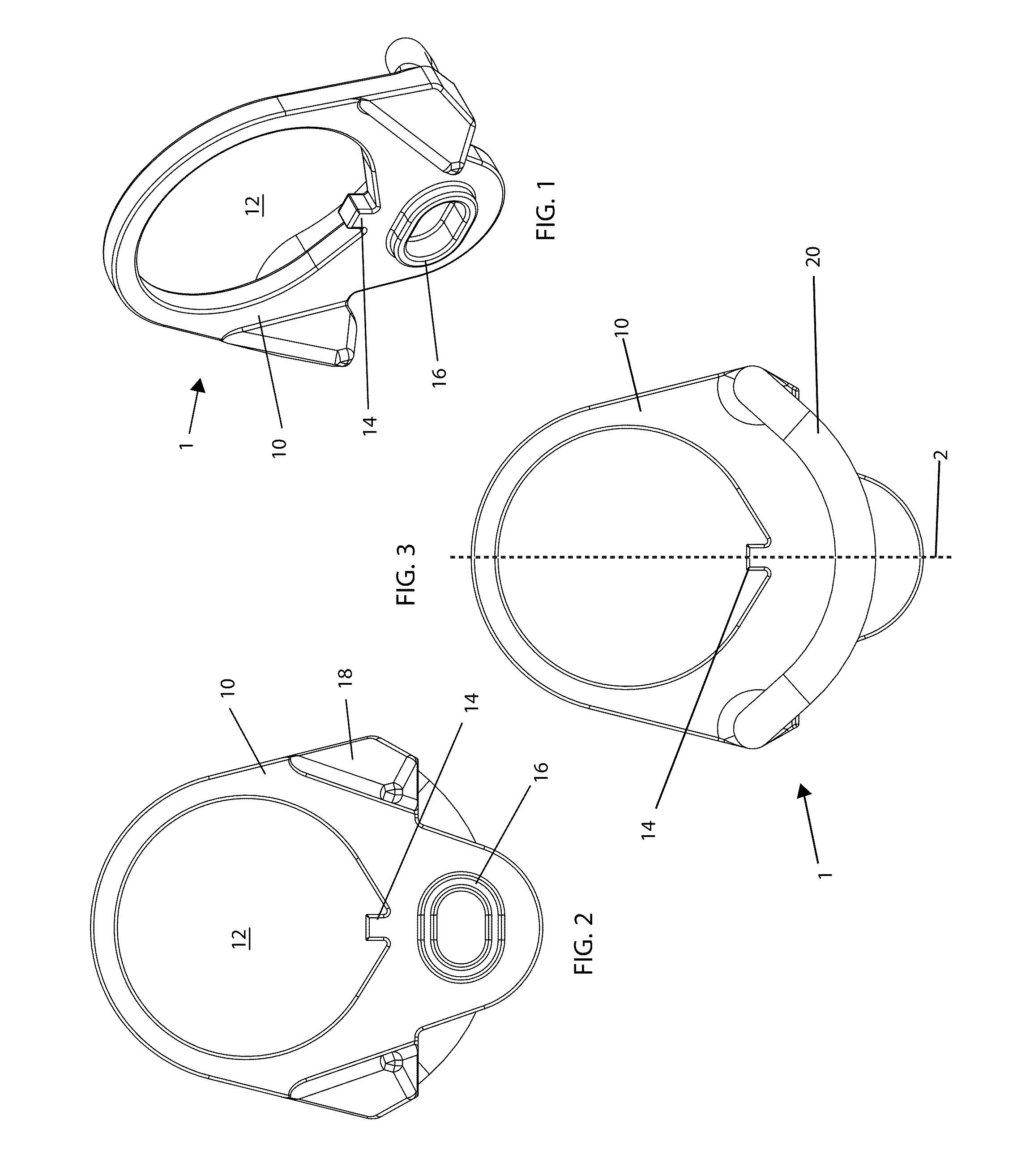
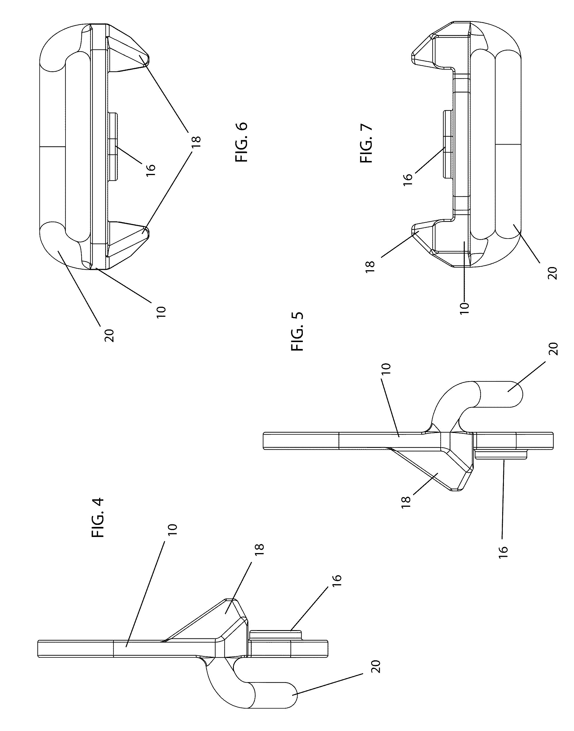
[0056]With reference to FIGS. 1-14 generally, the rear fitting 1 comprises a main fitting body 10 with an ovular shape. The wider portion of the main body circumscribes and defines an aperture 12, through which a receiver tube will slide when the fitting 1 is installed. A registration tab 14 is present in the lower part of aperture 12, extending from the circumference of the aperture, to register the sling fitting 1 on the receiver tube, as the receiver tubes for adjustable and collapsible stocks have a distal grove throughout the length of the tube. For fixed stock applications, where no such groove is present, registration tab 14 may be omitted. The lower portion of the fitting body 10 is narrower and presents a reg...


PUM


Abstract

The present invention is a sling system utilizing a rear sling fitting for a long firearm, such as a rifle. Such fittings typically are positioned between the stock and receiver. It presents a fitting body with an aperture to slide over a rifle receiver tube and a connection bar extending from a reverse of the fitting body. A point-type sling attachment may then be attached to the connection bar and be able to slide left and right across the back of the weapon, allowing for quickly adaptable left or right positioning of the weapon. Registration geometry may be added and positioned to further allow interface with weapon geometry and prevent rotation of the fitting during use. The connection bar may be positioned on another component of the weapon, such as the receiver or the stock, should the weapon not have a receiver extension tube. A convertible sling and forward sling mount are also disclosed for cooperative use with the fitting, completing the system.

Description

CROSS-REFERENCES TO RELATED APPLICATIONS[0001]The present Application claims priority as a non-provisional perfection of prior filed U.S. Provisional Application No. 61 / 145,106, filed Jan. 15, 2009, and incorporates the same herein by reference in its entirety.FIELD OF THE INVENTION[0002]The present invention relates to the field of firearms and more particularly relates to a sling fitting for attachment of a sling to a long firearm and an associated sling.BACKGROUND OF THE INVENTION[0003]Slings are regularly used with firearms to allow for a convenient method of carry and for weapon retention in dynamic environments. Traditional slings mount onto the bottom of a weapon at two points, fore and aft, allowing for suitable carry over long distances and may be used as a steadying aid to improve weapon accuracy. While it offers the user the ability to carry the weapon comfortably over the shoulder or securely across the back, the traditional, bottom-mounted 2-point sling hinders weapon u...

Claims


Application Information

Patent Timeline
Patent Type & Authority Applications(United States)
IPC IPC(8): F41C23/02
CPCF41C33/002F41C23/02
Inventor HALEY, TRAVIS D.CURRY, MATTHEW MATHEWKENT, ANDREWMAYBERRY, MICHAEL T.MORGAN, MICHAEL D.
Owner MAGPUL INDUSTRIES
Why Eureka
Try Eureka