Fluid dynamic bearing apparatus, spindle motor, and disk drive apparatus

a dynamic bearing and fluid technology, applied in the direction of sliding contact bearings, instruments, record information storage, etc., can solve the problems of reducing radial stiffness, rotating parts that include liquid lubricating fluid suffer from deterioration in rotation performance, rotating parts such as the shaft, or the sleeve, etc., to achieve high-quality labyrinth seals, reduce and prevent evaporation of lubricating oil, and ensure high-quality radial

Inactive Publication Date: 2011-01-27
NIPPON DENSAN CORP +1
View PDF25 Cites 18 Cited by
  • Summary
  • Abstract
  • Description
  • Claims
  • Application Information

AI Technical Summary

Benefits of technology

[0018]According to a preferred embodiment of the present invention, the labyrinth seal portion contributes to reducing and preventing evaporation of the lubricating oil. Moreover, the labyrinth seal portion is defined between the rotating member and the inner circumferential surface of ...

Problems solved by technology

However, in conventional fluid dynamic bearing apparatuses, if the axial dimension of the shaft is reduced to make the fluid dynamic bearing apparatus thinner, the length of the radial dynamic pressure bearing portion is inevitably reduced to cause a reduction in radial stiffness.
As a result, an external force, such a...

Method used


Image

  • Fluid dynamic bearing apparatus, spindle motor, and disk drive apparatus
  • Fluid dynamic bearing apparatus, spindle motor, and disk drive apparatus
  • Fluid dynamic bearing apparatus, spindle motor, and disk drive apparatus

Examples


Embodiment Construction

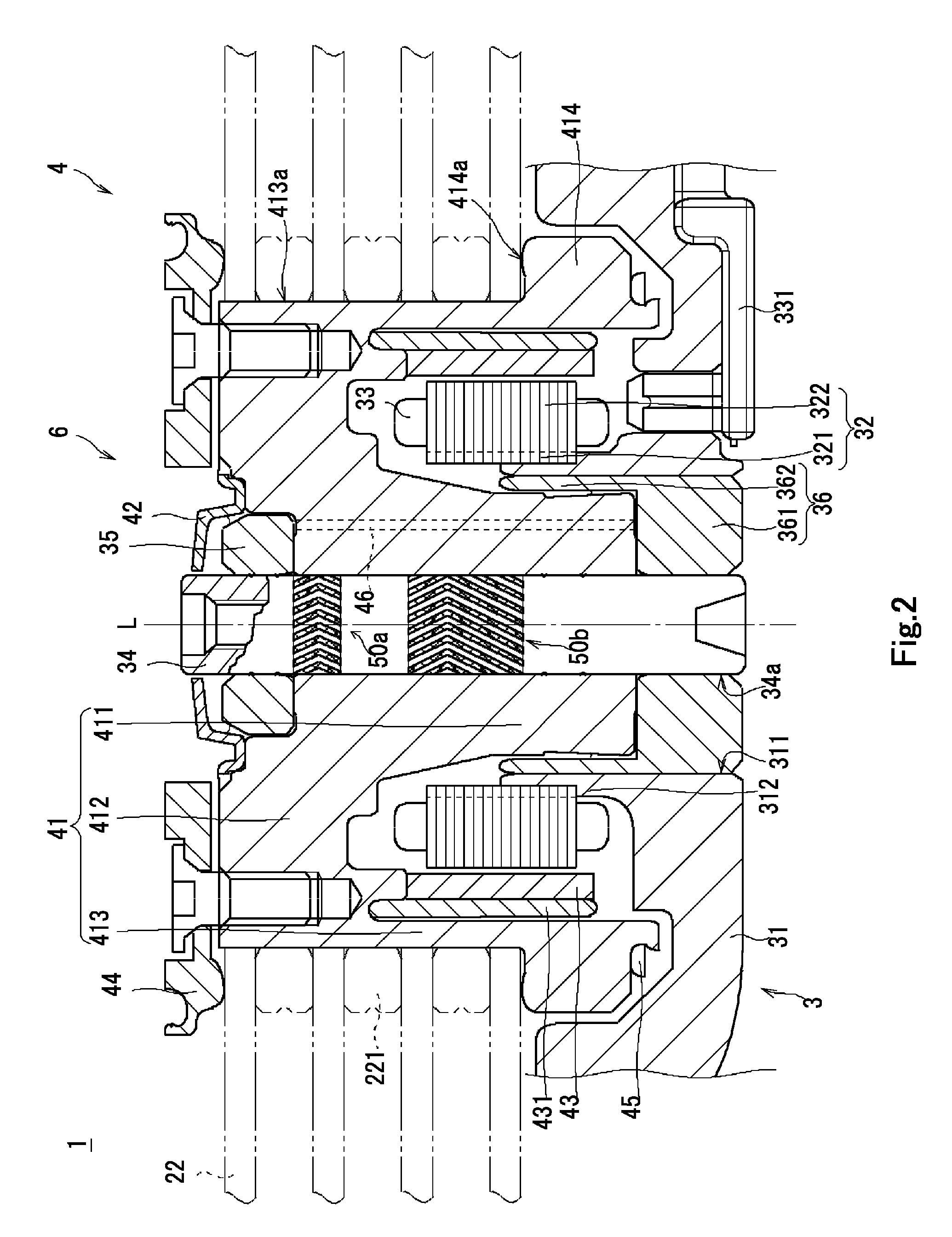
[0040]Hereinafter, preferred embodiments of the present invention will be described with reference to the accompanying drawings. Note that terms referring to “upward”, “downward”, “left”, “right”, etc., as used in the description of the present invention to describe relative positions or directions of different members are simply used with reference to the accompanying drawings, and should not be construed as describing relative positions or directions of those members when actually installed in a device. In the following description, for the sake of convenience in description, a side on which a rotor portion 4 is arranged and a side on which a stationary portion 3 is arranged along a central axis L are assumed to be an upper side and a lower side, respectively, as shown in FIG. 2.

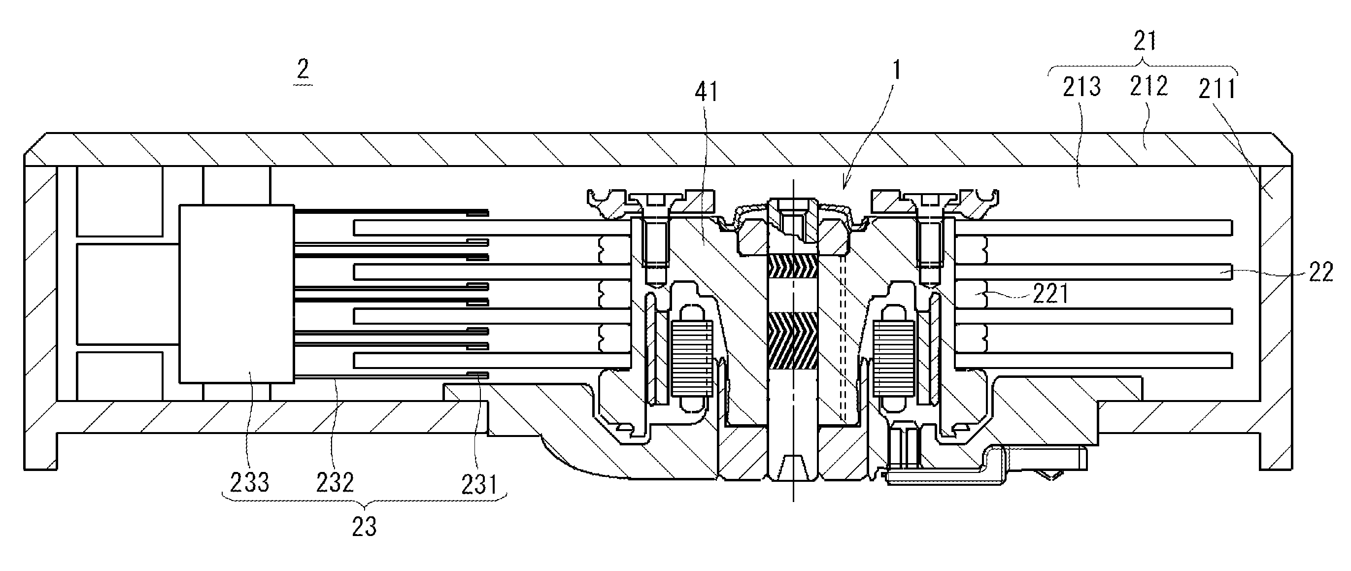
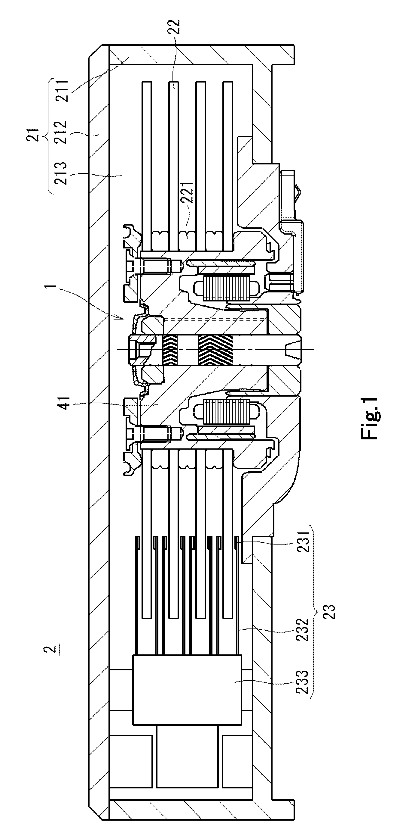
[0041]FIG. 1 is a cross-sectional view of a disk drive apparatus 2 including a spindle motor 1 according to an exemplary preferred embodiment of the present invention, taken along a plane including the cen...


PUM


Abstract

In a spindle motor, a capillary seal portion having a radial dimension that decreases in an axially downward direction, and a labyrinth seal portion arranged above the capillary seal portion are defined between an outer circumferential surface of a rotating member and an inner circumferential surface of a tubular portion. The capillary seal portion includes a liquid surface of a lubricating oil positioned therewithin. The radial dimension of the labyrinth seal portion is smaller than the radial dimension of an upper end portion of the capillary seal portion, so that the labyrinth seal portion contributes to reducing evaporation of the lubricating oil.

Description

1. FIELD OF THE INVENTION[0001]The present invention relates to a fluid dynamic bearing apparatus, a spindle motor including the fluid dynamic bearing apparatus, and a disk drive apparatus including the spindle motor.2. DESCRIPTION OF THE RELATED ART[0002]In recent years, there has been a great demand for an increase in density as well as for a reduction in size, thickness, and weight, for apparatuses designed to drive recording disks, such as magnetic disks and optical discs, as used in personal computers, car navigation systems, and so on. Accordingly, there has been a demand for an increase in a rotation rate of spindle motors used therein to rotate the disks, and an improvement in accuracy of rotational operation thereof. In order to satisfy such demands, fluid dynamic bearing apparatuses, in which a gap between a shaft and a sleeve is filled with a lubricating oil, are now often used in place of traditional ball bearings, as bearing apparatuses for the spindle motors.[0003]The ...

Claims


Application Information

Patent Timeline
IPC IPC(8): G11B5/02F16C32/06H02K5/167
CPCF16C17/107F16C33/1085F16C33/745F16C2370/12H02K5/1677H02K7/086G11B19/2036
Inventor YAMADA, HIROKIMIZUKAMI, JUNYAMORITA, TSUYOSHIMARUYAMA, TETSUYAIGUCHI, TAKURO
Owner NIPPON DENSAN CORP
Why Eureka
Try Eureka