Method And System For Dynamic Routing And/Or Switching In A Network

a dynamic routing and/or switching technology, applied in the field of communication systems, can solve the problems of blocking traffic, most of today's systems are increasingly becoming elements of complex networks,

Active Publication Date: 2011-01-27
AVAGO TECH INT SALES PTE LTD
View PDF19 Cites 52 Cited by
  • Summary
  • Abstract
  • Description
  • Claims
  • Application Information

AI Technical Summary

Benefits of technology

[0022]FIG. 5 is a flow chart illustrating exemplary steps for routing data based on one or more of routing parameters, costs associated with a device and / or data marking and / or tag information, in accordance with an embodiment of the invention.

Problems solved by technology

Fewer and fewer systems and devices are operated as stand-alone entities, and most of today's systems are increasingly becoming elements in complex networks.
Some network routers and / or switches, however, may block traffic.

Method used


Image

  • Method And System For Dynamic Routing And/Or Switching In A Network
  • Method And System For Dynamic Routing And/Or Switching In A Network
  • Method And System For Dynamic Routing And/Or Switching In A Network

Examples


Embodiment Construction

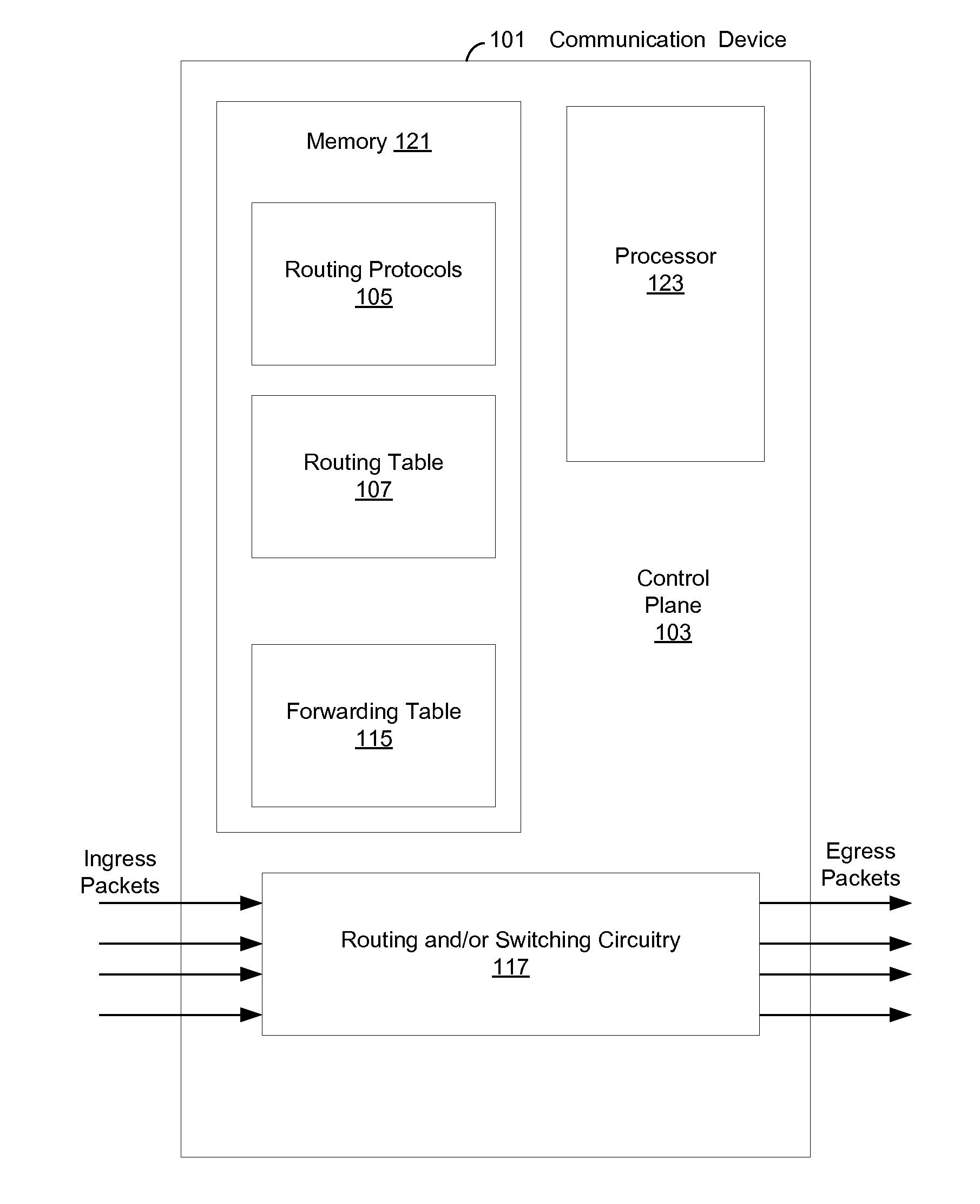
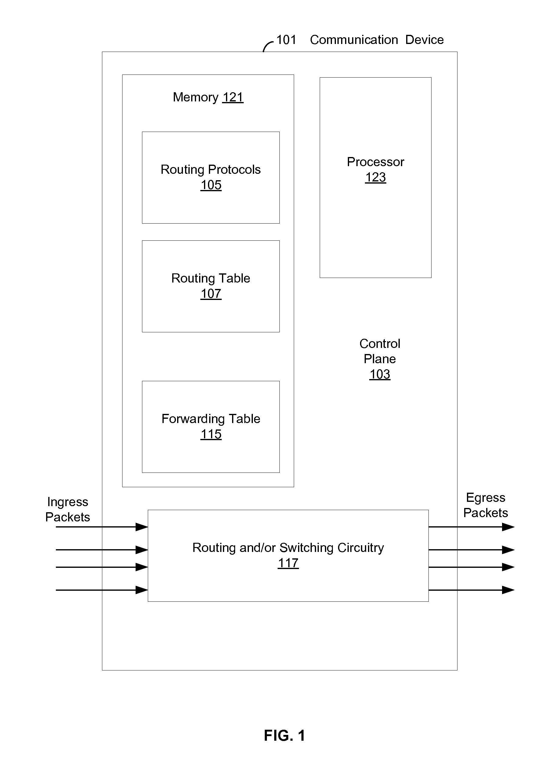
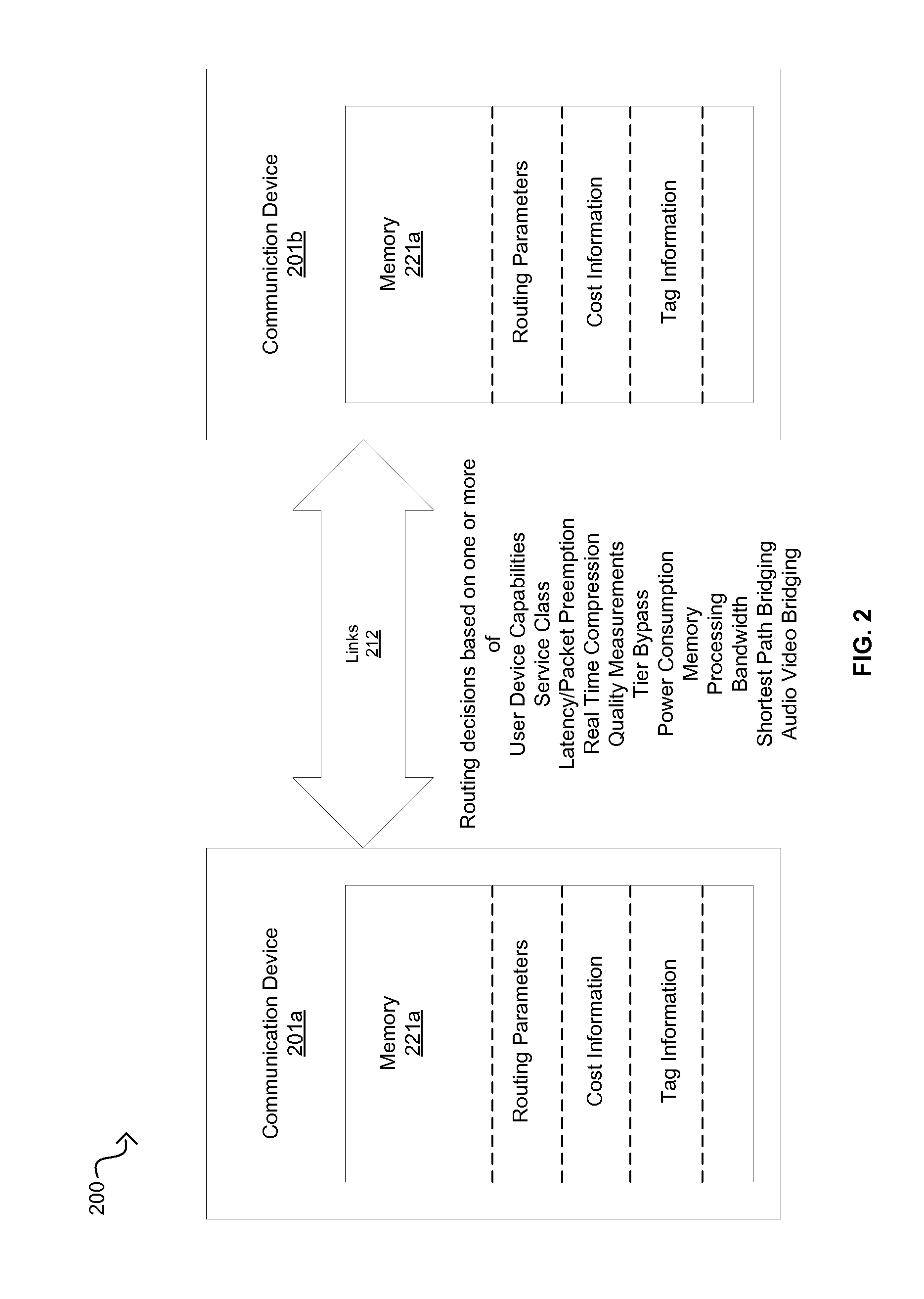
[0023]Certain embodiments of the invention can be found in a method and system for dynamic routing and / or switching in a network. In various embodiments of the invention, one or more processors and / or circuits in one or more of a plurality of communication devices may determine one or more routes over which packets may be communicated. The packets may be communicated between a first communication device of the plurality of communication devices and a second communication device of the plurality of communication devices. Furthermore, the packets may be communicated based on one or more of corresponding markings within the packets, routing parameters and / or costs that may be associated with utilizing the determined routes. At least one determined route may be selected for communicating the packets between the first communication device and the second communication device, and the packets may be communicated via the at least one selected route.

[0024]The routing parameters may comprise ...


PUM


Abstract

Communication devices may determine routes for packets based on packet marking, routing parameters and/or costs associated with routes. A route may be selected and the packets may be communicated via the selected route. The parameters may comprise service class, real time compression, packet preemption, quality measurements, tier bypass and/or power usage information. The costs may comprise capacity, efficiency and/or performance information for power usage, bandwidth, memory and/or processing. The marking may comprise traffic type, user device capabilities, service class, quality measurements, latency requirements and/or power usage information. Endpoint devices, software applications and/or service providers may insert the marking into packets. Routes may be determined and/or selected based on shortest path bridging, audio video bridging, the marking, the routing parameters and/or the costs. Parameters and/or costs may be received and/or discovered from communication devices. Packets and/or the marking may be parsed and/or inspected. Costs may be based on routing parameters.

Description

CROSS-REFERENCE TO RELATED APPLICATIONS / INCORPORATION BY REFERENCE[0001]This application makes reference to, claims priority to, and claims the benefit of U.S. Provisional Application Ser. No. 61 / 228,404, filed on Jul. 24, 2009.[0002]This patent application makes reference to:[0003]U.S. patent application Ser. No. 11 / 963,017 (Attorney Docket No. 18612U502), which was filed on Dec. 21, 2007;[0004]U.S. patent application Ser. No. 11 / 963,087 (Attorney Docket No. 18613U502), which was filed on Dec. 21, 2007;[0005]U.S. patent application Ser. No. ______ (Attorney Docket No. 20385US01), was filed on ______;[0006]U.S. patent application Ser. No. ______ (Attorney Docket No. 20379US01), which was filed on ______; and[0007]U.S. patent application Ser. No. ______ (Attorney Docket No. 20380US01), was filed on ______.[0008]Each of the above stated applications are hereby incorporated herein by reference in its entirety.FIELD OF THE INVENTION[0009]Certain embodiments of the invention relate to co...

Claims


Application Information

Patent Timeline
Patent Type & Authority Applications(United States)
IPC IPC(8): H04L12/56H04L45/74
CPCH04L45/00H04L45/302H04L45/124H04L45/74
Inventor MA, KENNETHCURRIVAN, BRUCEDIAB, WAEL WILLIAMKARAOGUZ, JEYHANKIM, YONGJOHAS TEENER, MICHAEL
Owner AVAGO TECH INT SALES PTE LTD
Why Eureka
Try Eureka