Methods and systems for carrying synchronization over ethernet and optical transport network

Active Publication Date: 2011-01-27
CIENA
View PDF14 Cites 25 Cited by
  • Summary
  • Abstract
  • Description
  • Claims
  • Application Information

AI Technical Summary

Benefits of technology

[0013]In another exemplary embodiment, a network element includes a plurality of ports; circuitry communicatively coupled to one or more of the plurality of ports, wherein the circuitry is configured to insert timing markers based upon a timing reference via a special symbol in a line encoding scheme associated with a signal. Optionally, the signal includes Ethernet or Optical Transport Network and the line encoding scheme includes any of 8B/10B, 64B/66B, 64B/65B, and 512B/513B. The timing markers may be each inserted at a defined interval based on the timing reference. The method may be performed by any of an Ethernet switch, a multi-service switch, a computer, a router, and an Optical Transport Network switch. Optionally, the signal includes Ethernet, and wherein the timing marker is inserted as the highest priority. The signal may include Ethernet, and wherein the timin

Problems solved by technology

Ethernet is becoming the common transport technology of choice in telecom networks; however it is unable to carry a true clock, such as a stratum clock, since Ethernet is asynchronous.
However, not all service providers trust this adaptive clock (especially over Ethernet) since these clocks do not have the quality or reliability of direct clocks.
Disadvantageously, this method requires a long period before it can lock onto a source clock and is susceptible to buffer overflow and underflow conditions.
OTN multiplexing does not, however, address lower-rate signals (such as Gigabit Ethernet (GbE), T

Method used


Image

  • Methods and systems for carrying synchronization over ethernet and optical transport network
  • Methods and systems for carrying synchronization over ethernet and optical transport network
  • Methods and systems for carrying synchronization over ethernet and optical transport network

Examples


Embodiment Construction

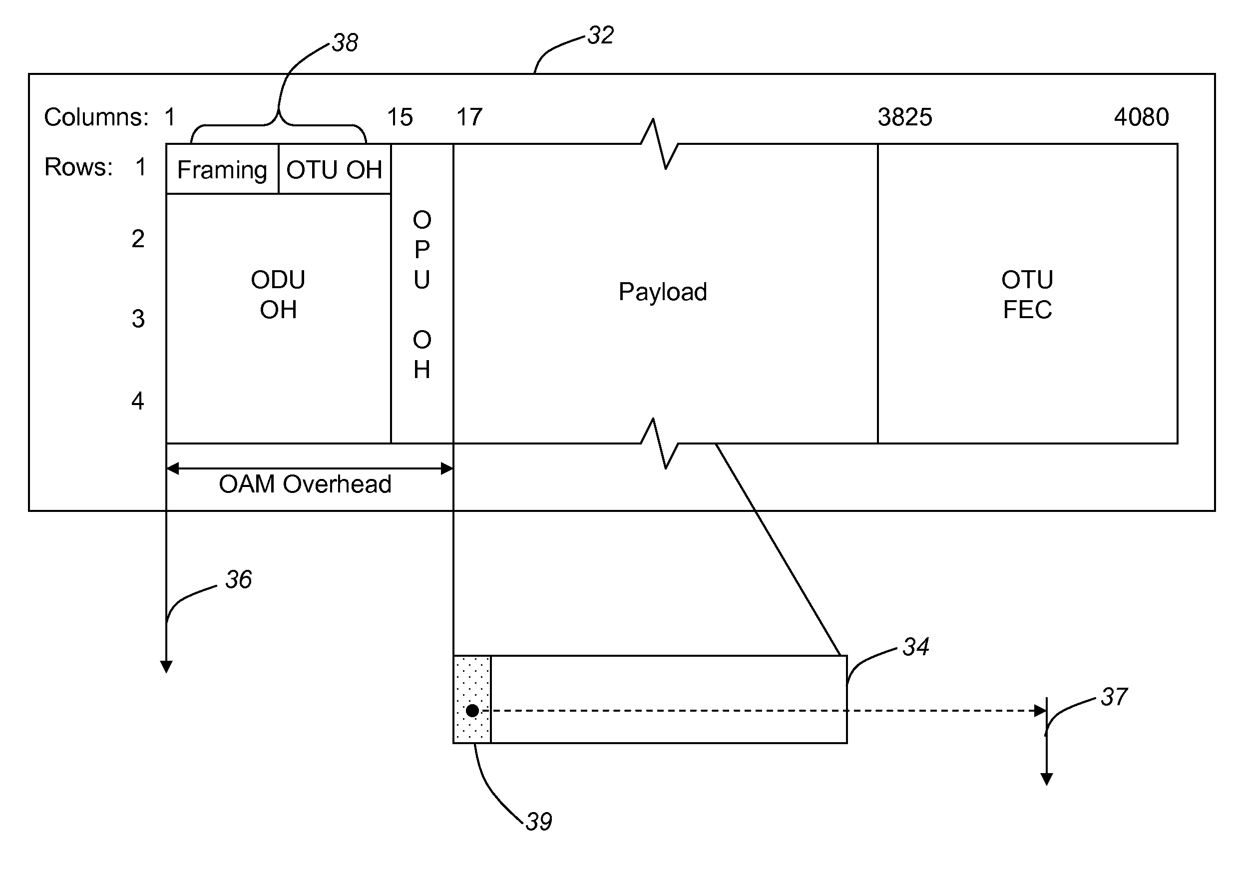
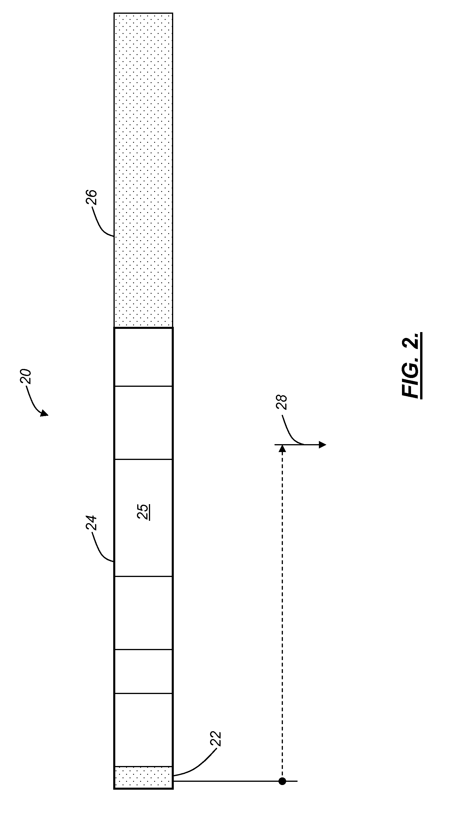
[0022]In various exemplary embodiments, the present invention relates to carrying synchronization through Ethernet, Optical Transport Network (OTN), and other asynchronous protocols. In one exemplary embodiment, timing markers or symbols are used in packets to enable a downstream device to recover timing based upon a time differential between markers or symbols. The present invention may reserve special Ethernet timing markers to mark timing within Ethernet and OTN, and secondarily creates frames within the Ethernet stream through the timing marker packets. The result is standard Ethernet with timing capability that can be transported over standard Ethernet links and / or OTN links. This timing capability can be utilized to carry synchronization (i.e. a hard clock) over asynchronous Ethernet and OTN streams. Advantageously, enabling Ethernet and OTN to carry solid synchronous information will de-risk switching from SONET / SDH to Ethernet and / or OTN for service providers. Although the p...


PUM


Abstract

The present disclosure relates to carrying synchronization through Ethernet, Optical Transport Network (OTN), and other asynchronous protocols. In one exemplary embodiment, timing markers or symbols are used in packets to enable a downstream device to recover timing based upon a time differential between markers or symbols. Advantageously, enabling Ethernet, OTN, etc. to carry synchronous information will de-risk switching from SONET/SDH to Ethernet and/or OTN for service providers. The present disclosure also includes frame decomposition scheme of the Ethernet stream. Ethernet packets are broken into fixed bandwidth and excess bandwidth. The fixed bandwidth is subdivided into fixed (negotiated) flits, with each flit corresponding to a specific user or combination of users like a private tunnel. This offers service providers a method to provide deterministic and more secure bandwidth over Ethernet to multiple clients.

Description

CROSS-REFERENCE TO RELATED APPLICATION(S)[0001]This application is a continuation-in-part of co-pending U.S. patent application Ser. No. 11 / 645,483 filed Dec. 26, 2006, and entitled “METHODS AND SYSTEMS FOR CARRYING SYNCHRONIZATION OVER ETHERNET AND OPTICAL TRANSPORT NETWORK,” the contents of which are incorporated in full by reference herein.FIELD OF THE INVENTION[0002]The present invention relates generally to timing distribution in networks. More specifically, the present invention provides timing distribution over Ethernet and Optical Transport Network (OTN) through the use of timing markers in the Ethernet frame or in the OTN header which provide a timing capability, and further a frame decomposition of the Ethernet packet.BACKGROUND OF THE INVENTION[0003]Networks need timing signals to operate, namely a common clock to reference when transmitting sampled data. For example, voice and video transmission and recovery require a common clock. Traditionally, the common clock in tele...

Claims


Application Information

Patent Timeline
IPC IPC(8): H04L12/56H04J3/06
CPCH04J3/0638H04J3/0647H04L25/4908H04J3/1658H04J2203/0085H04J3/0658
Inventor GAZIER, MICHAELDUNCAN, IAN H.GHODRAT, MORTEZA
Owner CIENA
Why Eureka
Try Eureka