Fuel cell and bipolar plate having manifold sump

a fuel cell and bipolar plate technology, applied in the field of fuel cells, can solve the problems of increasing the pressure loss across the fuel cell, water in the reactant gas, and “starvation” of the fuel cell,

Inactive Publication Date: 2011-01-27
AUDI AG
View PDF9 Cites 61 Cited by
  • Summary
  • Abstract
  • Description
  • Claims
  • Application Information

AI Technical Summary

Benefits of technology

[0004]The disclosed example bipolar plates and fuel cell are for facilitating reduction of wa

Problems solved by technology

One problem associated with fuel cells relates to water in the reactant gases.
In a supply manifold, the condensed water may block entry of fuel reactant gas into the flow field channels and cause “starvation” of the fue

Method used


Image

  • Fuel cell and bipolar plate having manifold sump
  • Fuel cell and bipolar plate having manifold sump
  • Fuel cell and bipolar plate having manifold sump

Examples


Embodiment Construction

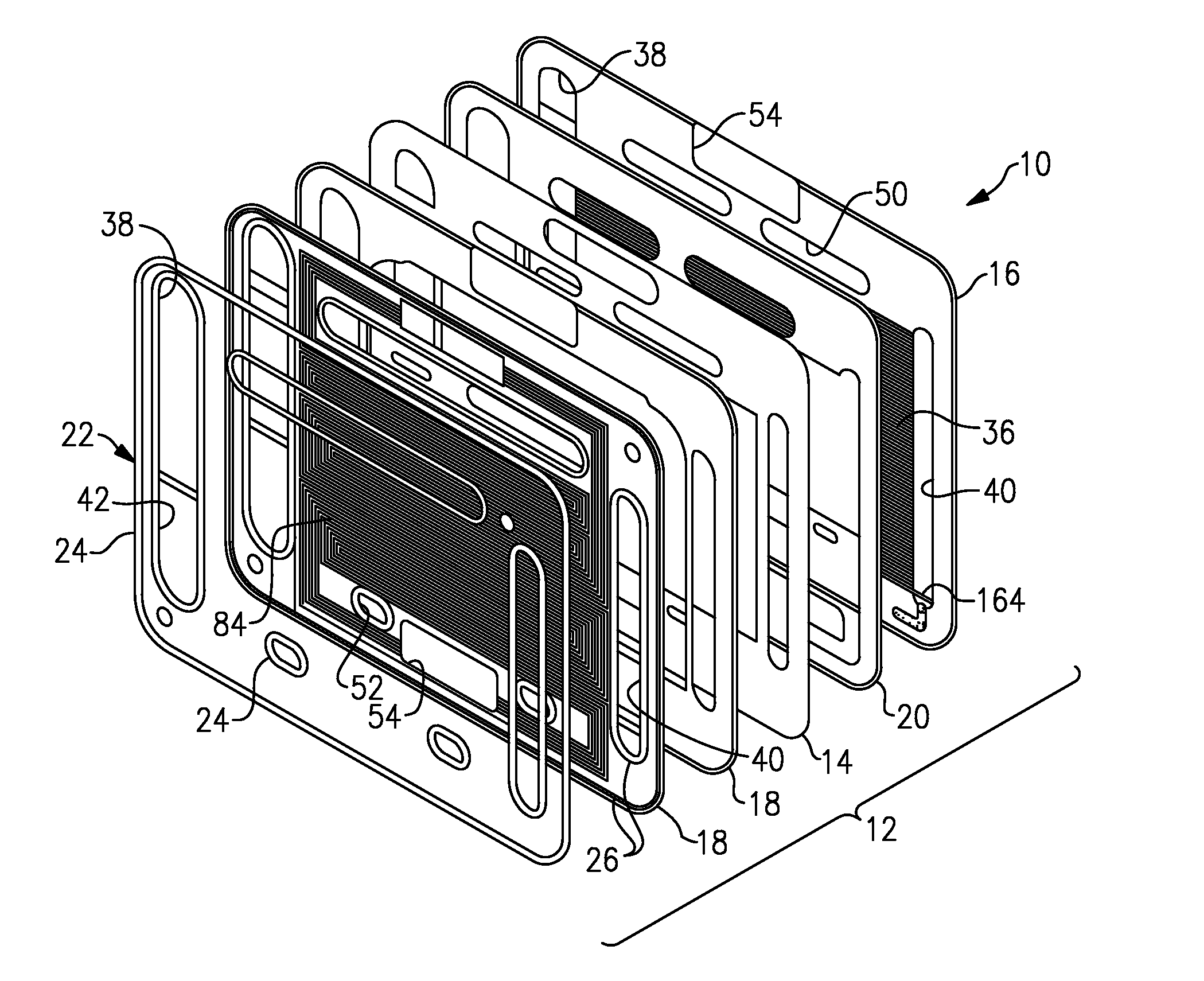
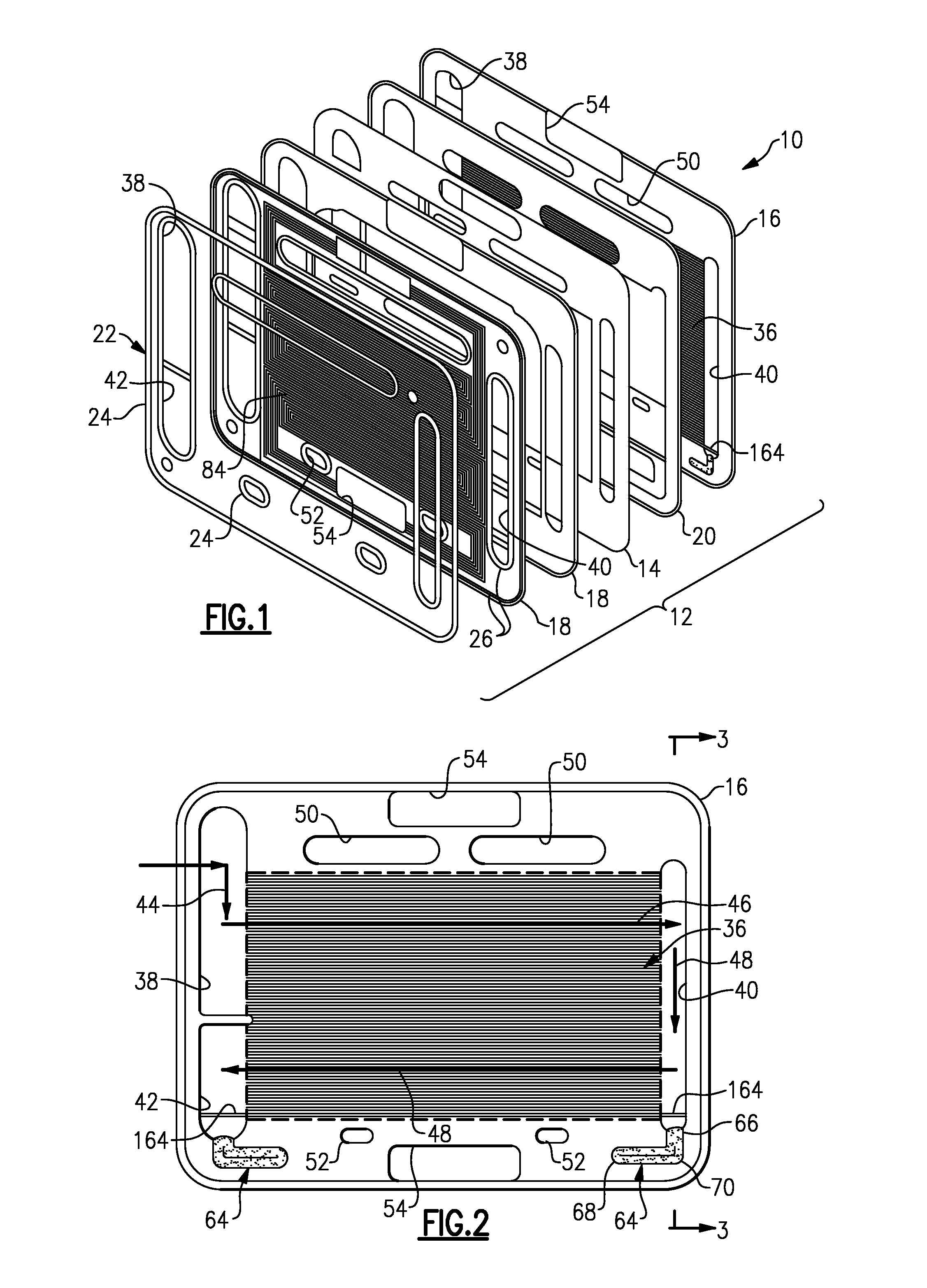
[0016]FIG. 1 schematically illustrates an exploded view of selected portions of an example fuel cell 10 for generating electricity. In the illustrated example, the fuel cell 10 includes at least one unitized cell 12. For example, a plurality of the unitized cells 12 may be used to form a fuel cell stack, depending on the desired amount of electricity to be generated. As is known, the unitized cell 12, or alternatively a fuel cell stack having multiple unitized cells 12, may be secured between pressure plates in a known manner to form the fuel cell 10. Furthermore, the fuel cell 10 may include various additional components that are not illustrated, such as components associated with the supply or return of reactant gases, coolant water, etc. Given this description, one of ordinary skill in the art would recognize that the disclosed examples are applicable to a variety of different fuel cell configurations.

[0017]In the disclosed example, the unitized cell 12 includes a membrane electr...


PUM


Abstract

A device for use in a fuel cell includes a bipolar plate having flow field channels, a manifold fluidly connected with the flow field channels for conveying a reactant gas, and a sump fluidly connected with the manifold.

Description

BACKGROUND OF THE DISCLOSURE[0001]This disclosure relates to fuel cells. More particularly, this disclosure relates to a fuel cell and bipolar plate having a manifold and a sump connected with the manifold for collecting water to facilitate reduction of an amount of the water in the manifold.[0002]Fuel cells are widely known and used for generating electricity for a variety of uses. Typically, a fuel cell unit includes an anode, a cathode, and an ion-conducting polymer exchange membrane (PEM) between the anode and the cathode. The anode and cathode are between bipolar plates (also referred to as transport plates) that include flow field channels and manifolds for circulating reactant gases through the flow field channels to the PEM and generating electricity in a known electro-chemical reaction.[0003]One problem associated with fuel cells relates to water in the reactant gases. Water vapor that is carried in the reactant gases may condense and collect in the manifolds. In a supply m...

Claims


Application Information

Patent Timeline
IPC IPC(8): H01M8/04
CPCH01M8/0258H01M8/04156H01M8/04783H01M8/04835Y02E60/521H01M8/1002H01M8/241H01M2008/1095H01M8/04843H01M8/1007Y02E60/50H01M8/2483H01M8/0267H01M8/2457H01M8/0263
Inventor LAKE, JEFFREY G.NIEZELSKI, DAVID A.
Owner AUDI AG
Why Eureka
Try Eureka