Method and system for displaying recovered energy for a hybrid electric vehicle

Active Publication Date: 2011-02-03
FORD GLOBAL TECH LLC
View PDF13 Cites 23 Cited by
  • Summary
  • Abstract
  • Description
  • Claims
  • Application Information

AI Technical Summary

Problems solved by technology

With regard to HEVs, it is known that some operators may not be able to achieve desired overall fuel economy, in part because of driving habits.
In many cases, operators are willing to modify their behavior, but are unable to translate recommended techniques into real changes in their driving hab

Method used


Image

  • Method and system for displaying recovered energy for a hybrid electric vehicle
  • Method and system for displaying recovered energy for a hybrid electric vehicle
  • Method and system for displaying recovered energy for a hybrid electric vehicle

Examples


Embodiment Construction

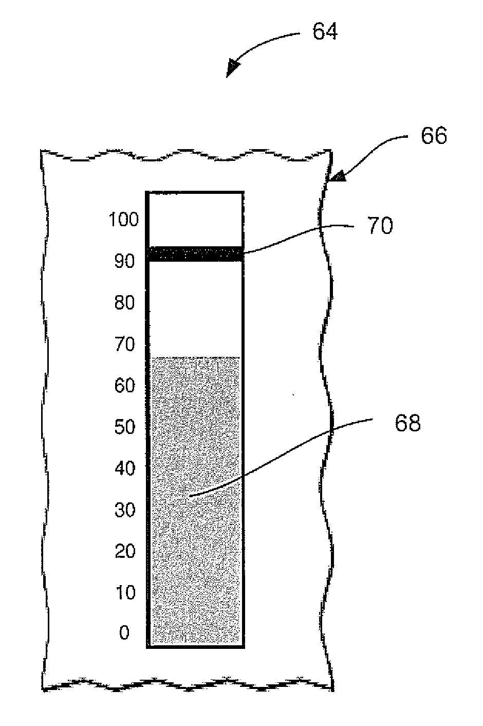
[0010]Hybrid vehicles may include conventional information displays, or gauges, with the goal of informing an operator about the hybrid driving states. The hybrid driving states may be displayed so that the operator may modify operation of the vehicle in order to improve the fuel economy (“FE”) of the vehicle. For example, many hybrid vehicles provide a conventional “power assist gauge” to indicate when the vehicle is operating an electric motor to assist in accelerating the hybrid vehicle. In addition, the conventional “power assist gauge” may indicate when the electric motor is being used to charge a battery of the vehicle during regenerative braking.

[0011]In combination with conventional instantaneous fuel economy gauges, such conventional information displays may give the operator a false sense of improved efficiency when braking. The false sense of improved fuel economy may be attributed to the fact that, during braking, a relatively high instantaneous fuel economy value may be...


PUM


Abstract

An information display configured to display one or more energy efficiency values of a vehicle. The information display system may comprise an information display configured to display an energy recovered indicator corresponding to a ratio of the braking energy recovered using a regenerative braking system. The information display may include both an overall energy recovered indicator and an instantaneous energy recovered indicator.

Description

BACKGROUND[0001]1. Technical Field[0002]One or more embodiments of the present disclosure relate to a system and method for indicating energy recovered by a regenerative braking system of a vehicle.[0003]2. Background Art[0004]Vehicles, whether passenger or commercial, include a number of gauges, indicators, and various other displays to provide the vehicle operator with information regarding the vehicle and its surroundings. With the advent of new technologies, such as hybrid electric vehicles (HEVs), has come a variety of new gauges and information displays that help operators to better learn the operation of these vehicles that utilize new technology. For example, many HEVs incorporate gauges that attempt to provide the operator with information on the various hybrid driving states. These gauges indicate to the operator when the vehicle is being propelled by the engine alone, the motor alone, or a combination of the two. Similarly, a display may indicate when the motor is operati...

Claims


Application Information

Patent Timeline
IPC IPC(8): B60Q1/00H02P3/14
CPCB60K6/445Y02T10/7275B60K2350/1092B60R16/0236B60T1/10B60T17/22B60W30/18127B60W2510/085Y02T10/6239Y02T10/92B60L7/18B60L7/26B60L11/005B60L11/123B60L11/14B60L11/16B60L15/2009B60L2240/12B60L2240/423B60L2240/443B60L2240/507B60L2250/16Y02T10/7077Y02T10/7005Y02T10/7022Y02T10/6217Y02T10/642B60K35/00Y02T10/72Y02T10/84B60L50/40B60L50/61B60L50/16B60L50/30B60K2370/174Y02T10/62Y02T10/64Y02T10/70Y02T10/7072B60W2510/244
Inventor CROMBEZ, DALE SCOTT
Owner FORD GLOBAL TECH LLC
Why Eureka
Try Eureka