Baffle plates for an ultraviolet reactor

Inactive Publication Date: 2011-02-03
EVOQUA WATER TECH PTE LTD
View PDF99 Cites 34 Cited by
  • Summary
  • Abstract
  • Description
  • Claims
  • Application Information

AI Technical Summary

Problems solved by technology

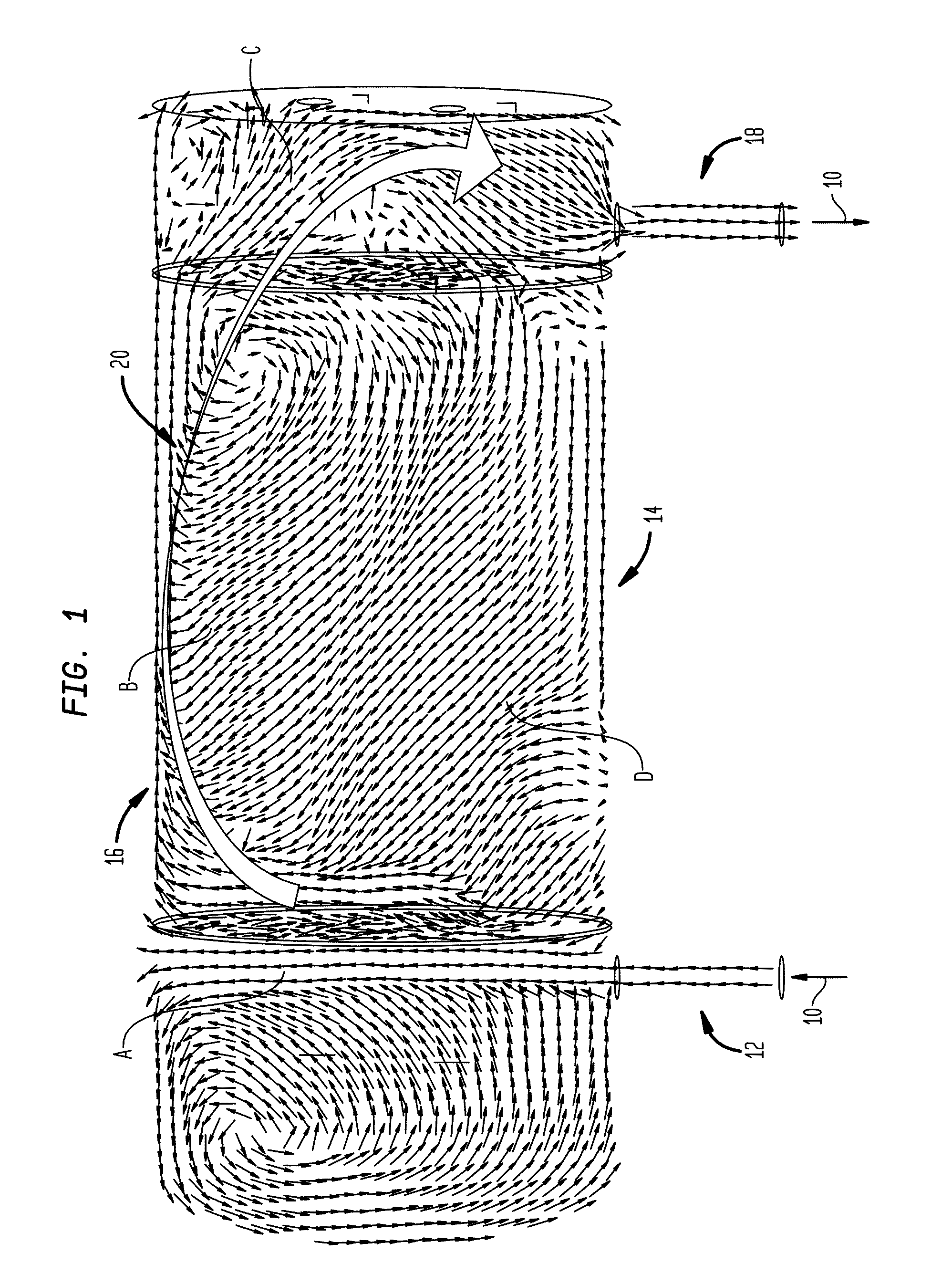
However, a desirable plug flow is not met by many available reactors due to the design of the baffle plates.
Thus, a substantial portion of the water in the UV chamber 14 is not subjected to suffici

Method used


Image

  • Baffle plates for an ultraviolet reactor
  • Baffle plates for an ultraviolet reactor
  • Baffle plates for an ultraviolet reactor

Examples


Embodiment Construction

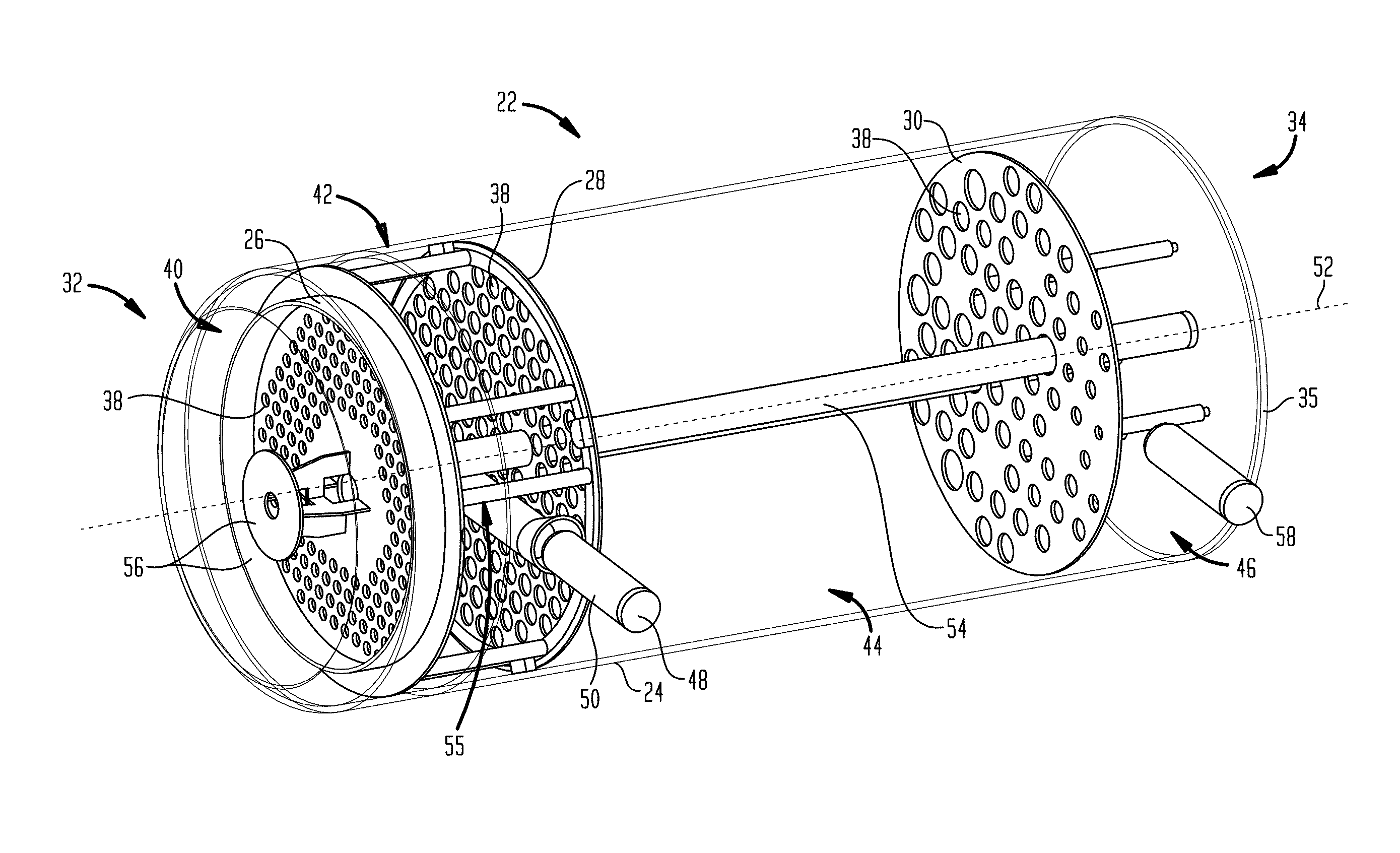
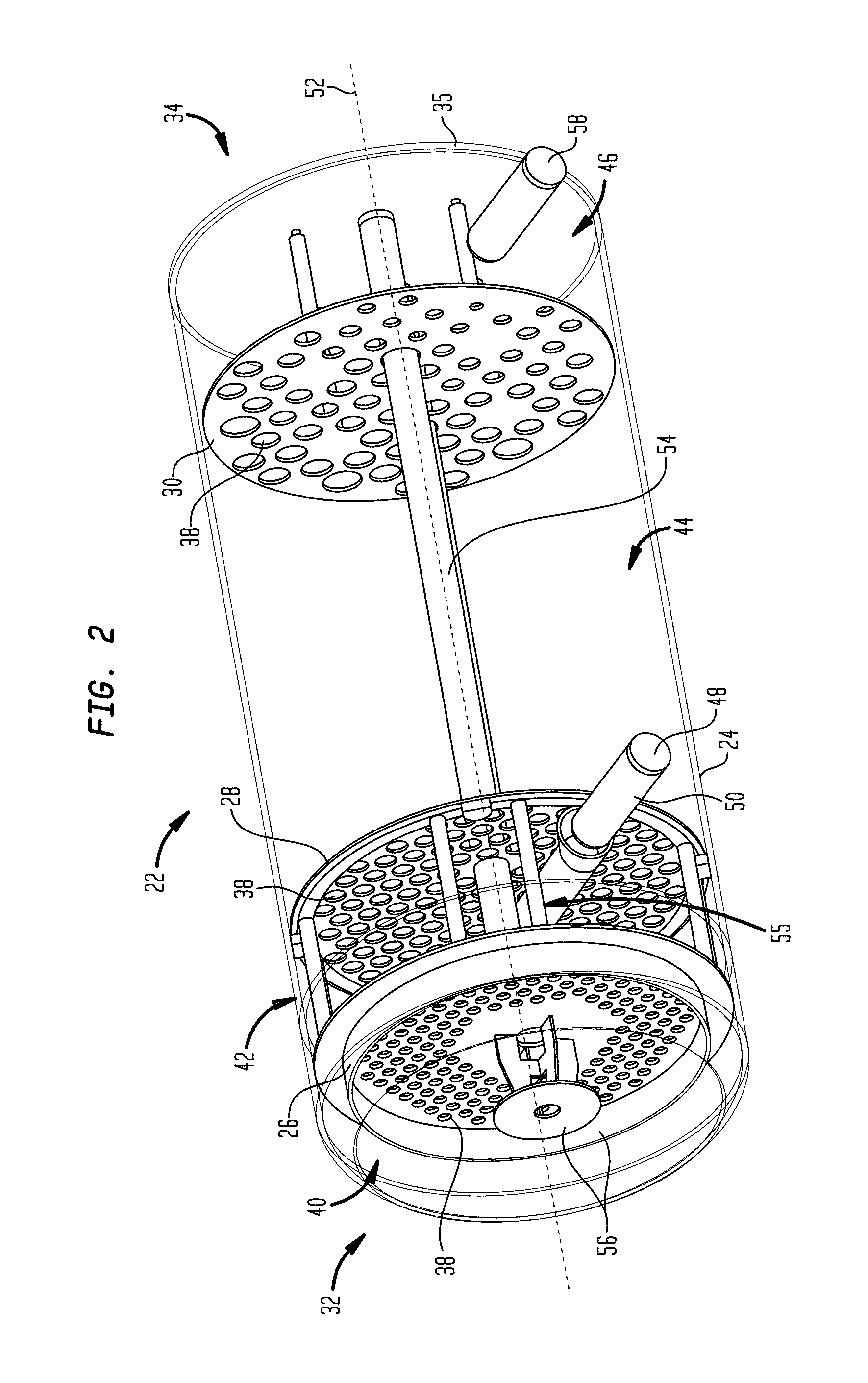
[0015]Before any embodiments of the invention are explained in detail, it is to be understood that the invention is not limited in its application to the details of construction and the arrangement of components set forth in the following description or illustrated in the following drawings. The invention is capable of other embodiments and of being practiced or of being carried out in various ways. Also, it is to be understood that the phraseology and terminology used herein is for the purpose of description and should not be regarded as limiting. The use of “including,”“comprising,” or “having” and variations thereof herein is meant to encompass the items listed thereafter and equivalents thereof as well as additional items. Unless specified or limited otherwise, the terms “mounted,”“connected,”“supported,” and “coupled” and variations thereof are used broadly and encompass direct and indirect mountings, connections, supports, and couplings. Further, “connected” and “coupled” are ...


PUM

PropertyMeasurementUnit
Angleaaaaaaaaaa
Angleaaaaaaaaaa
Flow rateaaaaaaaaaa

Abstract

An ultraviolet reactor for treating a fluid. The reactor includes a vessel having an inlet for receiving fluid and an outlet for discharging fluid. The reactor further includes an ultraviolet light source and baffle plates. The baffle plates include holes arranged in a predetermined pattern for providing plug flow in areas in the reactor near the ultraviolet light source.

Description

CROSS REFERENCE TO RELATED APPLICATIONS[0001]This application claims the benefit under 35 U.S.C. §119(e) of U.S. Provisional Application No. 61 / 230,040 entitled ULTRAVIOLET TANK BAFFLE DESIGN FOR ADVANCED OXIDATION PROCESS, filed on Jul. 30, 2009 and of U.S. Provisional Application No. 61 / 230,045 entitled ULTRAVIOLET TANK BUFFER DESIGN USING DIVERTER PLATE filed on Jul. 30, 2009 each of which is herein incorporated by reference in their entirety and to which this application claims the benefit of priority.FIELD OF THE INVENTION[0002]This invention relates to ultraviolet reactors, and more particularly, to baffle plates having a predetermined hole pattern for providing plug flow.BACKGROUND OF THE INVENTION[0003]An ultraviolet (UV) reactor may be used to disinfect water by rendering bacteria harmless or to energize oxidants to reduce total organic carbon (TOC). In certain applications, the UV reactor includes baffle plates to provide plug flow with respect to inlet water so as to maxi...

Claims


Application Information

Patent Timeline
IPC IPC(8): B01J19/12C02F1/32A61L2/10
CPCC02F1/325C02F2201/3223C02F2301/024C02F2301/02C02F2301/022C02F2201/328B01J19/006B01J19/123B01J19/2415B01J2219/00768A61L2/10B63B13/02B63B2013/005
Inventor YONG, ZHEE MIN JIMMYSTIBITZ, DAVIDCOULTER, BRUCE LEEHOOSIER, MICHAEL SCOTT
Owner EVOQUA WATER TECH PTE LTD
Why Eureka
Try Eureka