Image forming apparatus and method

a technology of image forming and forming tubes, which is applied in the direction of inking apparatus, printing apparatus, other printing apparatus, etc., can solve the problems of image quality decline, color bleeding, and droplets on the surface of recording media, so as to prevent image degradation, eliminate uneven surface feel, and prevent curing ink

Inactive Publication Date: 2005-09-01
FUJIFILM CORP
View PDF5 Cites 142 Cited by
  • Summary
  • Abstract
  • Description
  • Claims
  • Application Information

AI Technical Summary

Benefits of technology

[0012] The present invention has been contrived in view of such circumstances, and an object thereof is to provide an image forming apparatus and method whereby image deterioration caused by bleeding between colors can be prevented, while also preventing hardening of the ink inside the nozzles. It is also an object of the present invention to provide an image forming apparatus and method which uses an ink that is curable by application of energy, such as an ultraviolet curable ink, or a phase change type of ink, such as a solid ink, which can achieve image fixing creating a glossy appearance, while avoiding cracking or peeling of the ink surface, and which can also prevent image deterioration caused by mixing of colors between inks of different colors when forming a color image.

Problems solved by technology

However, the action of the heating unit disclosed in Japanese Patent Application Publication No. 2002-347232 contributes to the evaporation of the ink solvent, while making little contribution to curing of the ink.
Therefore, even if a heating unit is disposed immediately after each head, as illustrated in FIG. 7 of Japanese Patent Application Publication No. 2002-347232, droplets are still ejected from a subsequent (downstream) head while the ink discharged from an upstream head is in a liquid state on the recording medium, and hence there is interference between droplets on the surface of the recording medium, and bleeding of the colors due to color mixing.
Consequently, image quality declines.
This composition is, however, for irradiating an activating light beam after inks of all of the required colors for image formation have been ejected, and therefore, similarly to Japanese Patent Application Publication No. 2002-347232, color bleeding occurs due to mixing of the colors.
Japanese Patent Application Publication No. 2003-127517 discloses that light is irradiated from a curing light source by dividing the wavelength range and the irradiation time of the curing light source into two stages; however, it does not disclose the positional relationship between the head and the irradiation light source, and it is unclear at what timing the irradiation of light is actually performed.
Japanese Patent Application Publication No. 2003-191594 describes varying the irradiation conditions of the activating light source, namely, the irradiation time, the irradiation timing, the irradiation intensity, the irradiation energy, the type of light source, the irradiation surface area, the angle of incidence, and the wavelength characteristics; however, it does not disclose a composition for the apparatus which indicates the positional relationship between the irradiation light source and the head, and it is unclear what kind of device (apparatus) is used to achieve this.
Japanese Patent Application Publication No. 2003-182048 forms an image progressively by repeating the operations of a print section and an ultraviolet curing section, and therefore it is difficult to achieve high-speed output.
Furthermore, Japanese Patent Application Publication No. 2003-182048 does not describe the positional relationship between the head and the UV irradiation device.
However, if ultraviolet light of an amount required to fix the ink is irradiated in the vicinity of the head, then the ink inside the nozzle is hardened by the random reflection from the print medium, and the like, and this can lead to discharge errors.
However, if an ultraviolet curable ink is used within the technical scope described in Japanese Patent Application Publication No. 2001-1512, problems arise in that fracturing and peeling occurs in the ink surface when the ink is flattened by pressurization.

Method used


Image

  • Image forming apparatus and method
  • Image forming apparatus and method
  • Image forming apparatus and method

Examples


second embodiment

General Composition of Inkjet Recording Apparatus

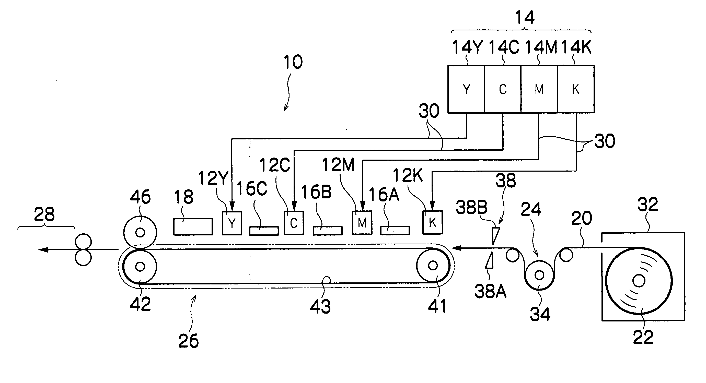
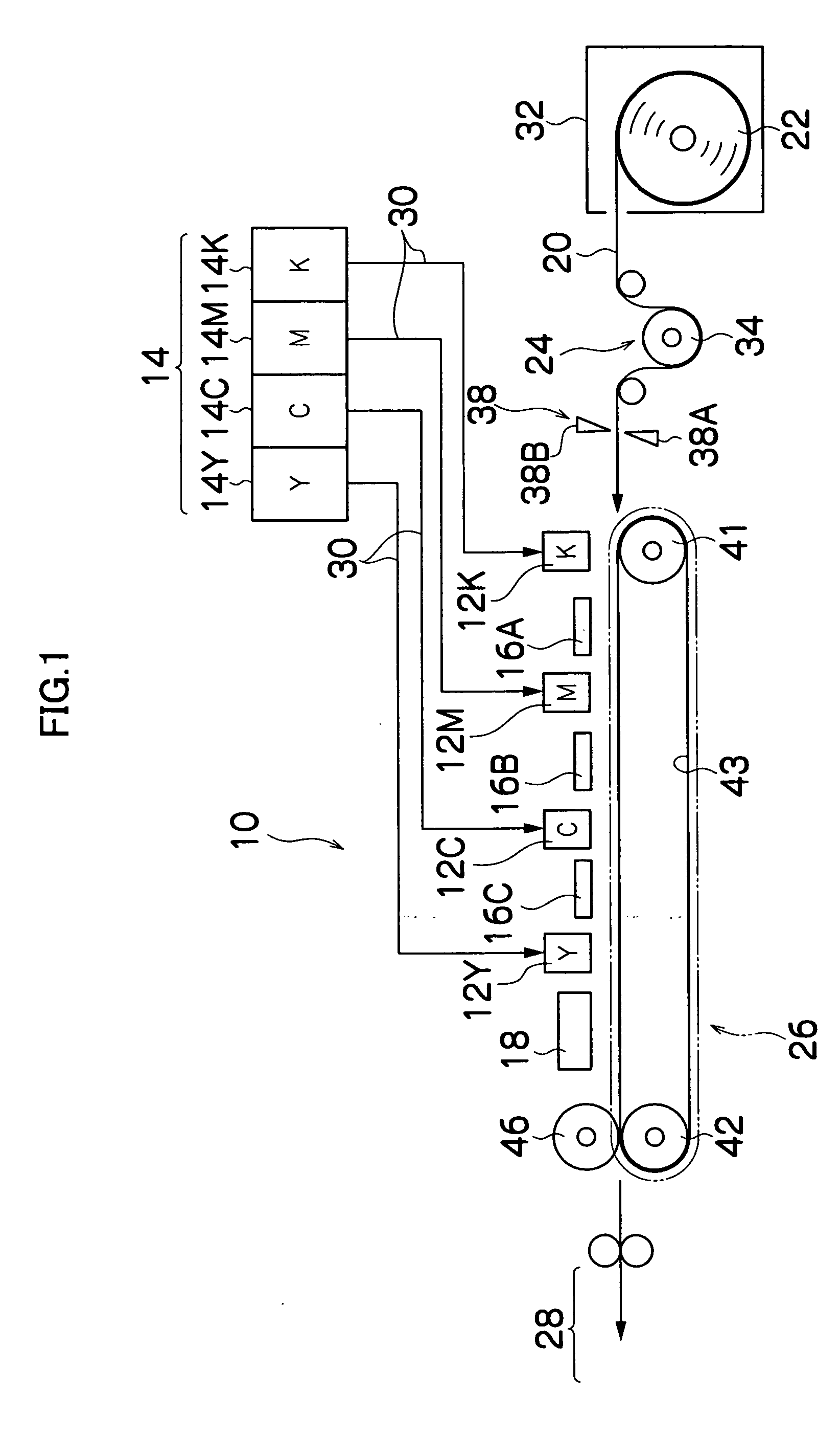
[0176]FIG. 16 is a diagram of the general composition of an image forming apparatus according to a second embodiment of the present invention. Parts which are the same or similarly to those in the compositional example illustrated in FIG. 1 are labeled with the same reference numerals and further description thereof is omitted here.

[0177] As shown in FIG. 16, this inkjet recording apparatus 210 comprises: a plurality of inkjet heads (hereafter, called “heads”) 12K, 12M, 12C, 12Y, 12CL provided corresponding to respective ink colors, namely, black (K), magenta (M), cyan (C), yellow (Y) and clear (CL); an ink storing and loading unit 14 for storing ultraviolet curable ink (so-called “UV ink”) to be supplied to the heads 12K, 12M, 12C, 12Y and 12CL; semiliquid forming light sources 16A, 16B, 16C, 16D, 16E disposed respectively on the downstream side of each head; a pressurizing and fixing unit 17 disposed downstream of the semiliquid f...


PUM


Abstract

The image forming apparatus comprises: an ink discharge device comprising a plurality of full line type inkjet heads arranged separately for a plurality of inks of different colors, each of the inkjet heads having a nozzle row in which a plurality of nozzles for discharging droplets of the ink toward a surface of a recording medium are arranged through a length corresponding to a full width of the recording medium; an ink supply device which supplies ultraviolet curable inks of corresponding colors to the inkjet heads; a conveyance device which causes the inkjet heads and the recording medium to move relatively to each other by conveying at least one of the recording medium and the inkjet heads in a direction substantially perpendicular to a breadthways direction of the recording medium; a first curing device which irradiates ultraviolet light for causing the droplets of the ink, deposited on the surface of the recording medium by one of the inkjet heads on an upstream side in a direction of relative conveyance of the recording medium with respect to the inkjet heads, to semi-cure to a degree whereby the droplets of the ink discharged from the inkjet head on the upstream side do not mix on the surface of the recording medium with the droplets of the ink discharged by a next one of the inkjet heads situated on a downstream side in the direction of relative conveyance, the first curing device comprising an ultraviolet light source including a group of light emitting elements arranged in a linear form and disposed between the inkjet heads of the respective colors; and a second curing device which irradiates ultraviolet light for performing main curing of the droplets of the ink on the recording medium to a degree whereby image degradation does not occur upon subsequent handling of the cured droplets of the ink, the second curing device being disposed after one of the inkjet heads situated in a furthest downstream position of the inkjet heads.

Description

BACKGROUND OF THE INVENTION [0001] 1. Field of the Invention [0002] The present invention relates to an image forming apparatus and method, and more particularly to an image forming apparatus and an image forming method which forms images on a recording medium by discharging ink from an inkjet head. Furthermore, the present invention relates to an image forming apparatus and an image forming method suitable for forming color images by discharging inks of a plurality of colors onto a recording medium by means of full line type inkjet heads having a nozzle row spanning a length corresponding to the entire printable width. [0003] 2. Description of the Related Art [0004] There is an inkjet type image forming apparatus using ultraviolet curable ink (so-called UV ink). Japanese Patent Application Publication No. 2002-347232 discloses a technology comprising a heating unit for heating the ink provided between a full line type recording unit which discharges light-curable ink, and a light i...

Claims


Application Information

Patent Timeline
Patent Type & Authority Applications(United States)
IPC IPC(8): B41J2/01B41J2/155B41J11/00
CPCB41J2/155B41J11/0015B41J2202/20B41J2002/14459B41J11/002B41J2/16585B41J2002/16591B41J11/00214B41J11/00218B41J11/00212
Inventor KONNO, MASAAKIKADOMATSU, TETSUZO
Owner FUJIFILM CORP
Why Eureka
Try Eureka