Insulation layer formation method, member with insulation layer, resistance measurement method and junction rectifier

a technology of insulation layer and member, applied in the direction of superimposed coating process, liquid/solution decomposition chemical coating, instruments, etc., can solve the problems of insulation layer of the related art with several problems, peeling or cracking of the insulation layer with respect to the conductor layer, and risk of defects

Pending Publication Date: 2022-08-11
NEXT INNOVATION
View PDF0 Cites 0 Cited by
  • Summary
  • Abstract
  • Description
  • Claims
  • Application Information

AI Technical Summary

Problems solved by technology

However, the insulation layer of the related art has several problems.
For example, the insulation layer, which is formed of a resin layer, has a coefficient of thermal expansion different from that of the conductor layer so that there is a risk of defects such as peeling or cracking of the insulation layer with respect to the conductor layer.
Further, when the insulation layer is resin, heat resistance or weather resistance is not sufficient so that deterioration is accelerated due to repeated thermal expansion, shrinkage, wetting, and drying due to environments of high temperature and high humidity.
Therefore, there is a risk of defects such as peeling

Method used


Image

  • Insulation layer formation method, member with insulation layer, resistance measurement method and junction rectifier
  • Insulation layer formation method, member with insulation layer, resistance measurement method and junction rectifier
  • Insulation layer formation method, member with insulation layer, resistance measurement method and junction rectifier

Examples


examples

[0101]Hereinafter, the present disclosure will be described in more detail with reference to Examples. However, each of the Examples is not intended to limit the present disclosure.

[0102]In the Examples and the Comparative Examples, a processing order of the first step to the third step, measurement of the insulating property, measurement of a withstanding voltage, and evaluation of a rust preventive property are performed as follows.

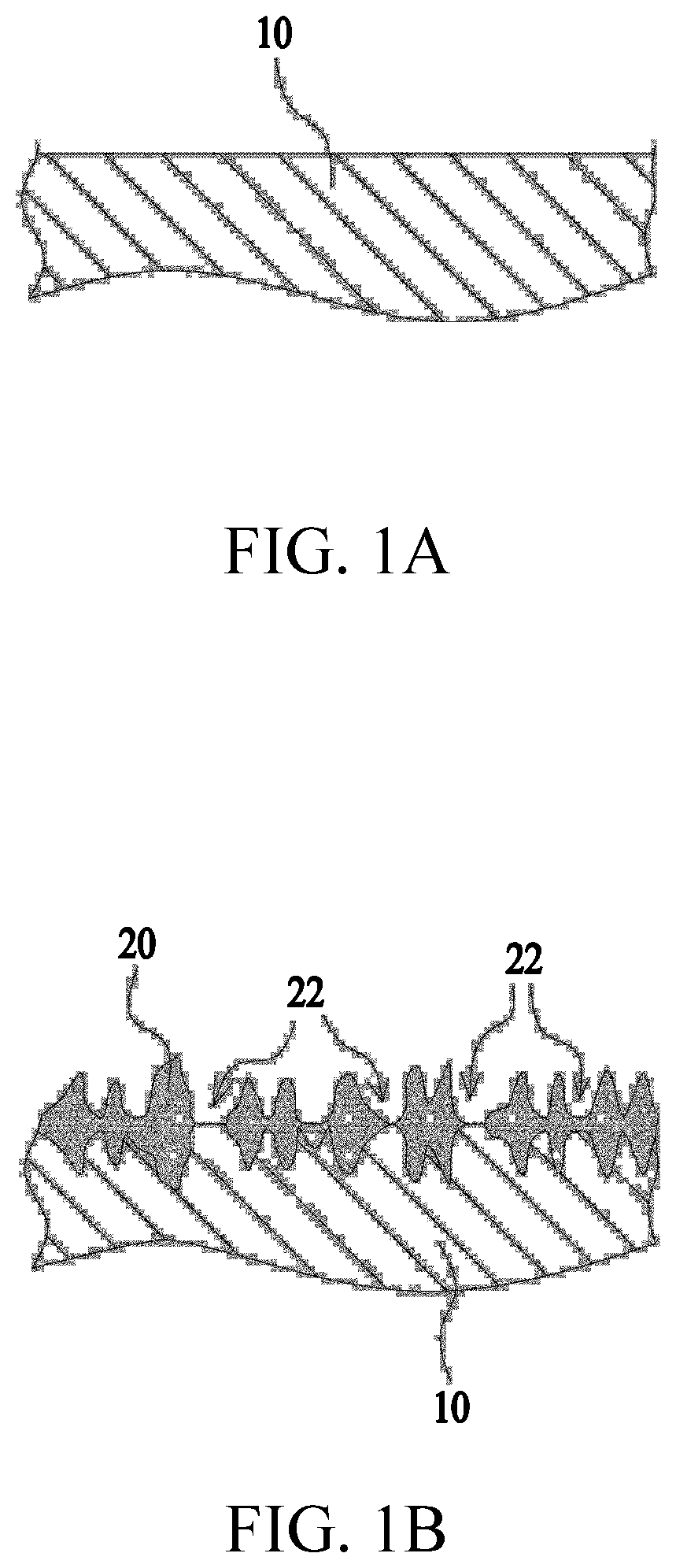
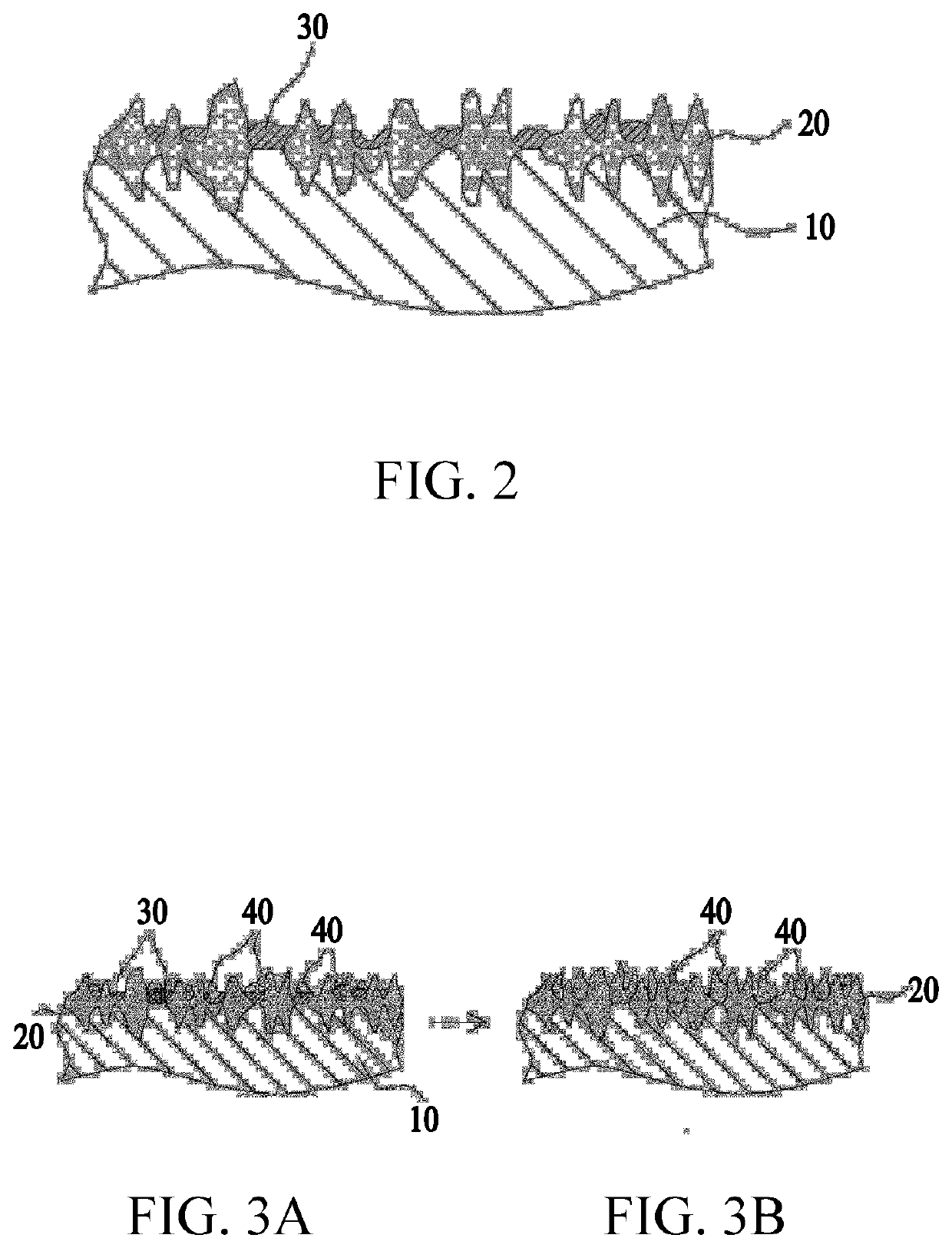
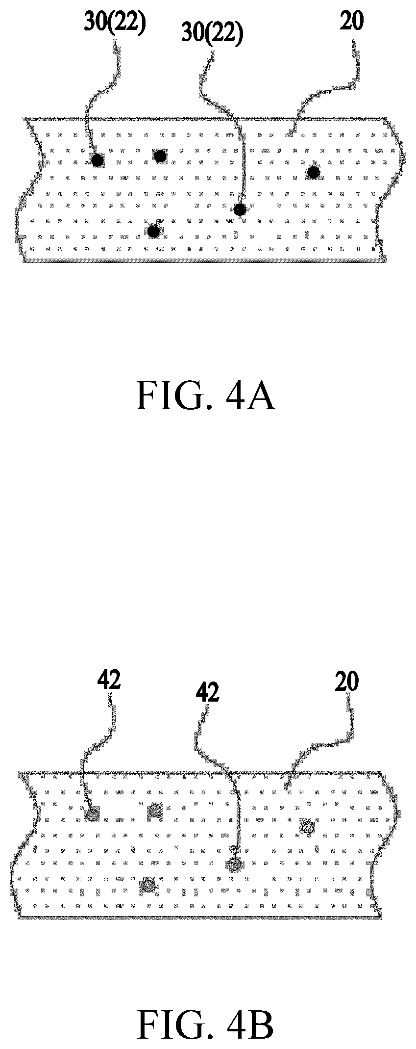
[0103][Base Material]

[0104]A SPCC plate with a thickness of 0.475 mm, a width of 30 mm, and a length of 100 mm was used as a base material for forming an insulation layer.

[0105][First Step]

[0106]On the SPCC plate, as a phosphating layer, any one layer of a manganese phosphate layer, a zinc manganese phosphate layer, and a zinc phosphate layer was formed. Here, when the manganese phosphate layer was formed, the SPCC plate was dipped in a manganese phosphate treatment solution for 11 minutes at 95° C. As the manganese phosphate treatment solution, a solut...


PUM

PropertyMeasurementUnit
Areaaaaaaaaaaa
Thicknessaaaaaaaaaa
Electrical resistanceaaaaaaaaaa

Abstract

An insulation layer formation method comprises: a first step in which a surface treatment is applied to a base material to form thereon a high-resistance layer having high electric resistivity; a second step in which metal plating parts are formed on the base material that has undergone the first step in such a manner as to allow a high-resistance layer to be formed thereon; and a third process in which a high-resistance layer is formed on the base material that has undergone the second step.

Description

CROSS-REFERENCE TO RELATED APPLICATIONS[0001]This application is a national phase entry under 35 U.S.C. § 371 of International Patent Application PCT / JP2019 / 027619, filed Jul. 11, 2019, designating the United States of America and published as International Patent Publication WO 2020 / 013304 A1 on Jan. 16, 2020, which claims the benefit under Article 8 of the Patent Cooperation Treaty to Japanese Patent Application Serial No. 2018-131913, filed Jul. 11, 2018.TECHNICAL FIELD[0002]The present disclosure relates to an insulation layer formation method, etc.BACKGROUND[0003]In the related art, a multi-layered printed wiring board formed by alternately laminating conductor layers and insulation layers has been proposed (for example, refer to Patent Document 1). The insulation layer of the multi-layered printed wiring board is formed by overlapping a thermosetting resin layer and a liquid crystal polymer resin layer.[0004]Further, a thin metal package in which an insulation layer is formed ...

Claims


Application Information

Patent Timeline
IPC IPC(8): C23C28/00H01L49/00H05K3/44H05K1/05C25D5/48C25D5/02C23C22/07G01R27/02G01R31/12
CPCC23C28/34H01L49/00H05K3/44H05K1/053C23C28/32C25D5/48H05K2203/1476C23C22/07G01R27/02G01R31/1227H05K2203/0776H05K2203/072H05K2203/0723C25D5/02G01R27/025H05K1/0271H05K2201/068H05K2203/0315H05K3/188H05K3/181H05K3/384C25D3/30C25D3/20C25D3/22C25D3/12C25D3/562C23C18/50C23C18/32C23C18/31C23C18/168C23C22/18H10N99/00
Inventor MICHIWAKI, HIROSHI
Owner NEXT INNOVATION
Why Eureka
Try Eureka